 Tech Volt Lab Automation | PLC | SCADA | Electrical | Electronics

Related Articles
A Capacitor Calculator helps electronics technicians, electrical engineers, maintenance professionals, automation specialists, and students calculate key capacitor values without having to perform manual calculations. It can determine capacitance, stored charge, stored energy, capacitive reactance, RC time constant, and the equivalent value of capacitors connected in series or parallel. Capacitors are used in power supplies, electronic circuits, motor-starting systems, power-factor correction panels, signal filters, timing circuits, DC links, snubbers, and energy-storage applications. Selecting the wrong capacitance, voltage rating, dielectric type, or ripple-current capability can lead to poor performance, overheating, reduced service life, or component failure.
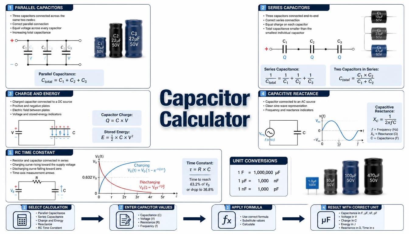
This guide explains the most useful capacitor formulas, unit conversions, series and parallel combinations, reactance, energy storage, and RC timing. The calculated value should be treated as a design reference and checked against the capacitor manufacturer’s datasheet and the real voltage, frequency, temperature, ripple current, and operating duty.
What Is a Capacitor Calculator?
A Capacitor Calculator is an electrical and electronics tool used to solve relationships involving capacitance, voltage, charge, frequency, resistance, time, and energy. Capacitance is measured in farads, although most practical components use microfarads, nanofarads, or picofarads.
A capacitor stores electric charge between conductive surfaces separated by an insulating dielectric. Its ability to store charge is represented by capacitance. A larger capacitance stores more charge at the same voltage, but the component’s construction and ratings determine whether it is suitable for a particular circuit.
The calculator can also combine several capacitor values. Parallel capacitors add directly, while series capacitors produce a total capacitance lower than the smallest individual value. For AC circuits, the tool can calculate how capacitance and frequency determine capacitive reactance.
How Does a Capacitor Calculator Work?
The calculator first asks which capacitor property must be determined. It then displays the inputs required for that calculation and converts the entered values into compatible base units before applying the relevant formula.
- Select capacitance, charge, energy, reactance, or RC timing.
- Select a series or parallel capacitor connection.
- Enter voltage, frequency, resistance, or capacitor values.
- Select the correct unit for every input.
- Calculate the requested result.
- Review the result in F, µF, nF, or pF.
- Compare the value with an available capacitor and its datasheet.
The numerical capacitance alone does not completely define a capacitor. Voltage rating, polarity, tolerance, equivalent series resistance, ripple current, temperature range, dielectric, lifetime, and safety classification can be equally important.
Step-by-Step Process
- Identify which capacitor value or circuit property is required.
- Read the capacitance and voltage rating from the component or datasheet.
- Check whether the capacitor is polarized or non-polarized.
- Convert capacitance units where required.
- Enter all capacitor values for a series or parallel network.
- Enter operating frequency when calculating reactance.
- Enter resistance when calculating an RC time constant.
- Enter voltage when calculating charge or stored energy.
- Calculate and review the result. Select a real capacitor with suitable electrical and thermal ratings.
Capacitor Calculator Formula
Capacitance from Charge and Voltage
C = Q ÷ V
Capacitance equals stored electric charge divided by the voltage across the capacitor. One farad stores one coulomb of charge when the potential difference is one volt.
Stored Charge
Q = C × V
This formula calculates charge in coulombs when capacitance is entered in farads and voltage in volts.
Energy Stored in a Capacitor
E = ½ × C × V2
Stored energy increases with capacitance and with the square of voltage. A relatively small capacitance charged to a high voltage can retain hazardous energy after power has been disconnected.
Capacitors Connected in Parallel
Ctotal = C1 + C2 + C3 + …
Parallel capacitors have the same voltage across them, and their capacitances add directly. The combined bank must still satisfy voltage, ripple-current, balancing, and connection requirements.
Capacitors Connected in Series
1 ÷ Ctotal = (1 ÷ C1) + (1 ÷ C2) + (1 ÷ C3) + …
The equivalent capacitance of a series connection is lower than the smallest individual capacitor. Voltage may not divide equally in real circuits because of capacitance tolerance and leakage-current differences.
Two Capacitors Connected in Series
Ctotal = (C1 × C2) ÷ (C1 + C2)
This simplified product-over-sum equation can be used when exactly two capacitors are connected in series.
Capacitive Reactance
XC = 1 ÷ (2 × π × f × C)
Capacitive reactance is the opposition a capacitor presents to sinusoidal AC at a specified frequency. Reactance decreases when capacitance or frequency increases.
Ideal Capacitor Current in an AC Circuit
I = V ÷ XC
I = 2 × π × f × C × V
These formulas calculate ideal RMS capacitor current for a sinusoidal voltage when RMS voltage and frequency are used. Actual capacitor current can be affected by harmonics, voltage distortion, equivalent series resistance, and circuit conditions.
RC Time Constant
τ = R × C
The RC time constant describes the charging or discharging rate of a capacitor through a resistor. After one time constant, a charging capacitor reaches approximately 63.2% of its final ideal voltage.
Capacitor Charging Voltage
VC(t) = VS × [1 − e−t÷RC]
This formula gives the ideal voltage across an initially discharged capacitor while it charges through a resistor from a fixed DC supply.
Capacitor Discharge Voltage
VC(t) = V0 × e−t÷RC
This equation calculates the remaining ideal capacitor voltage during discharge through a resistor. Real circuits may include leakage, load variation, switch resistance, and other discharge paths.
Formula Explanation
| Symbol | Description |
|---|---|
| C | Capacitance in farads (F) |
| Ctotal | Equivalent capacitance of a capacitor network |
| Q | Electric charge in coulombs (C) |
| V | Voltage across the capacitor in volts |
| E | Stored energy in joules (J) |
| XC | Capacitive reactance in ohms (Ω) |
| f | Frequency in hertz (Hz) |
| I | Ideal capacitor current in amperes |
| R | Resistance in ohms |
| τ | RC time constant in seconds |
| t | Elapsed time in seconds |
| VS | Applied DC supply voltage |
| V0 | Initial capacitor voltage before discharge |
| e | Mathematical constant, approximately 2.71828 |
Common Capacitance Unit Conversions
| Capacitance Unit | Equivalent Value |
|---|---|
| 1 farad (F) | 1,000,000 microfarads |
| 1 microfarad (µF) | 0.000001 farad |
| 1 microfarad (µF) | 1,000 nanofarads |
| 1 nanofarad (nF) | 0.001 microfarad |
| 1 nanofarad (nF) | 1,000 picofarads |
| 1 picofarad (pF) | 0.001 nanofarad |
Interactive Capacitor Calculator
Use the calculator below to calculate capacitance, charge, stored energy, capacitive reactance, RC time constant, or the equivalent value of series and parallel capacitors.
⚡ Capacitor Calculator
Calculate capacitive reactance, stored energy, charge, or equivalent capacitance.
Capacitor Result
Enter values and press Calculate.
Reactance: Xc = 1 ÷ (2πfC)
Charge: Q = C × V
Energy: E = ½CV²
Parallel: Ct = C1 + C2 + ...
Series: 1/Ct = 1/C1 + 1/C2 + ...
Example 1 — Capacitor Stored Energy and Charge
Given:
- Capacitance = 0.002 F
- Voltage = 10 V
Stored Energy:
Charge:
The calculated stored energy is 0.1 J, and the capacitor charge is 0.02 C. A practical capacitor must have a suitable voltage rating, appropriate capacitance tolerance, compatible polarity, acceptable ripple current, and the correct capacitor type for the circuit.
Example 2 – Capacitors Connected in Parallel
Given:
- C1 = 100 µF
- C2 = 220 µF
- C3 = 470 µF
Ctotal = 100 + 220 + 470
Ctotal = 790 µF
The total nominal capacitance is 790 µF. Parallel capacitors share the applied voltage, while ripple current may divide between them according to ESR, wiring impedance, temperature, capacitance tolerance, and construction.
Example 3 – Two Capacitors Connected in Series
Given:
- C1 = 100 µF
- C2 = 220 µF
Ctotal = (100 × 220) ÷ (100 + 220)
Ctotal = 22,000 ÷ 320 = 68.75 µF
The equivalent series capacitance is 68.75 µF. It is lower than either individual capacitor. Series voltage does not necessarily divide equally in a real circuit, particularly with electrolytic capacitors, because leakage and tolerance vary. Balancing components and manufacturer guidance may be required.
Example 4 – Capacitive Reactance at 50 Hz
Given:
- Capacitance = 10 µF or 0.00001 F
- Frequency = 50 Hz
- Applied sinusoidal voltage = 230 V RMS
XC = 1 ÷ (2 × 3.1416 × 50 × 0.00001)
XC ≈ 318.31 Ω
I = 230 ÷ 318.31 ≈ 0.723 A
The ideal capacitive reactance is approximately 318.31 Ω and the ideal RMS current is approximately 0.723 A. A real capacitor must be specifically rated for the applied AC voltage, frequency, current, duty, temperature, and intended application.
Practical Field Considerations for Capacitor Selection
A capacitor’s voltage rating must exceed the maximum voltage it will experience, including ripple, switching spikes, transients, and possible supply variation. DC and AC voltage ratings are not automatically interchangeable. Use a capacitor designed and approved for the intended waveform and circuit.
Polarized electrolytic capacitors require correct terminal orientation. Applying reverse voltage can damage the dielectric and may cause leakage, heating, venting, or rupture. Non-polarized film or ceramic capacitors are used where the voltage reverses continuously, subject to their individual ratings.
Capacitance can change with tolerance, temperature, ageing, applied voltage, and frequency. Some ceramic dielectrics lose a significant portion of their nominal capacitance under DC bias. A component marked with the required value may therefore provide less effective capacitance in its operating circuit.
Equivalent series resistance causes heating when ripple current flows through a capacitor. This is especially important in VFD DC links, switching power supplies, inverter circuits, and high-frequency filters. Both ripple-current rating and ESR must be checked rather than choosing a component based on capacitance alone.
Motor start and motor run capacitors are not interchangeable. A start capacitor is normally intended for short-duration duty, while a run capacitor is designed for continuous AC operation. Always use the motor or equipment manufacturer’s specified capacitance, voltage, duty, and construction.
Capacitors can retain dangerous voltage after a circuit is switched off. Use approved discharge arrangements and verify voltage with a suitable instrument before touching terminals or working on the connected equipment.
Applications of a Capacitor Calculator
Electronics Applications
- Power-supply smoothing and filtering
- Signal coupling and decoupling
- RC timing and delay circuits
- Oscillators and frequency filters
- Energy storage and pulse circuits
Industrial Applications
- VFD and inverter DC-link capacitors
- Motor start and run capacitors
- Power factor correction equipment
- Snubber and surge-suppression circuits
- Industrial power supplies and UPS systems
Automation Applications
- PLC power-supply filtering
- Sensor signal conditioning
- Relay and coil suppression networks
- Timing and pulse-generation circuits
- Control-board troubleshooting
Advantages of a Capacitor Calculator
- Converts between common capacitance units.
- Calculates charge and stored energy.
- Combines series and parallel capacitors.
- Calculates reactance at a selected frequency.
- Determines RC time constants.
- Reduces manual unit-conversion mistakes.
- Supports circuit design and troubleshooting.
Limitations
- Basic formulas describe ideal capacitor behaviour.
- Real capacitors include ESR, leakage, and inductance.
- Effective capacitance can change with voltage and temperature.
- Series voltage sharing may not be equal.
- Reactance calculations may not include harmonics or waveform distortion.
- The result does not select the dielectric or construction type.
- Manufacturer ratings must be checked before installation.
Common Mistakes
- Confusing microfarads, nanofarads, and picofarads.
- Using a DC-rated component in an unsuitable AC application.
- Reversing a polarized electrolytic capacitor.
- Ignoring voltage-rating margin and transients.
- Adding series capacitances as though they were parallel.
- Assuming series voltage divides equally.
- Ignoring ESR and ripple-current rating.
- Interchanging motor start and run capacitors.
- Assuming a discharged circuit contains no stored voltage.
- Selecting a replacement from capacitance alone.
Capacitor behavior changes with frequency, which you can verify with the Frequency Calculator. In AC systems, compare reactive effects with the Power Factor Calculator.
Frequently Asked Questions
What is a Capacitor Calculator?
A Capacitor Calculator determines values such as capacitance, stored charge, energy, capacitive reactance, RC time constant, and equivalent series or parallel capacitance.
What is the unit of capacitance?
The SI unit is the farad, represented by F. Practical capacitors commonly use microfarads, nanofarads, or picofarads.
How do capacitors add in parallel?
Parallel capacitances add directly. The total capacitance equals the sum of all individual capacitor values.
How do capacitors combine in series?
Add the reciprocals of the capacitances and take the reciprocal of the result. Total series capacitance is lower than the smallest individual capacitor.
What is capacitive reactance?
Capacitive reactance is a capacitor’s opposition to sinusoidal AC at a specified frequency. It decreases as capacitance or frequency increases.
What does an RC time constant mean?
The time constant equals resistance multiplied by capacitance. After one time constant, an ideal charging capacitor reaches about 63.2% of its final voltage.
Can a higher-voltage capacitor replace a lower-voltage one?
It may be acceptable when capacitance, type, polarity, ESR, ripple current, physical size, and other requirements match. Confirm replacement suitability with manufacturer data.
Why can a capacitor remain dangerous after power is removed?
A capacitor stores electrical energy and may retain hazardous voltage after disconnection. Use an approved discharge method and verify the voltage before working on the circuit.
Related Electronics Calculators
- Ohm’s Law Calculator
- Frequency Calculator
- Capacitive Reactance Calculator
- RC Time Constant Calculator
- Energy Cost Calculator
- Power Factor Calculator
Helpful Electronics Resources
Conclusion
A Capacitor Calculator provides a convenient way to calculate capacitance, stored charge, energy, capacitive reactance, RC time constant, and equivalent series or parallel values. These calculations are useful during circuit design, maintenance, component replacement, and electronics training.
A correct capacitance result does not automatically identify the correct physical component. Voltage rating, dielectric, polarity, tolerance, ripple current, ESR, frequency, temperature, lifetime, and safety classification must also match the application.
Tech Volt Lab provides practical electrical, electronics, and automation calculators for engineers, electricians, PLC technicians, maintenance professionals, and students. Use the calculated value as an engineering reference and confirm critical capacitor specifications with manufacturer documentation before installation.
Explore More Engineering Calculators
Discover more free electrical and automation calculators designed for electricians, PLC programmers, maintenance technicians, and engineers.
View All Calculators