 Tech Volt Lab Automation | PLC | SCADA | Electrical | Electronics

Related Articles

A Transformer Calculator helps electricians, electrical engineers, panel builders, maintenance technicians, automation professionals, and students calculate important transformer values without repeating lengthy manual calculations. Depending on the selected function, it can determine transformer kVA, primary current, secondary current, voltage ratio, turns ratio, efficiency, regulation, or approximate terminal fault current. Transformer calculations are required when selecting distribution transformers, control transformers, isolation transformers, protective devices, cables, busbars, and switchgear. An incorrect transformer rating can result in overheating, excessive voltage drop, poor motor starting, nuisance tripping, reduced service life, or insufficient capacity for future loads.
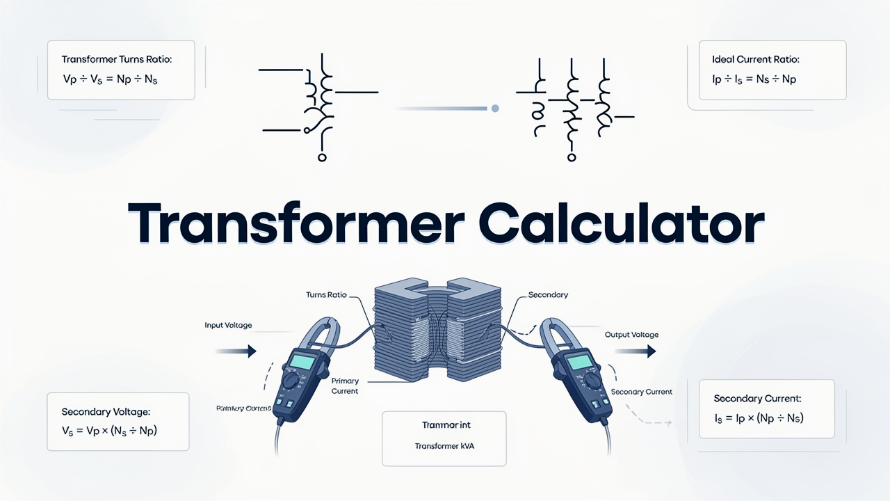
This guide explains the main single-phase and three-phase transformer formulas, shows how to calculate winding currents and turns ratio, and provides practical examples. Calculator results should be used as preliminary engineering values and checked against the transformer nameplate, manufacturer data, applicable standards, installation conditions, and load characteristics.
What Is a Transformer Calculator?
A Transformer Calculator is an electrical calculation tool used to solve the relationships between transformer voltage, current, apparent power, turns ratio, efficiency, and impedance. It can work with both single-phase and balanced three-phase transformers when the correct system type and units are selected.
Transformers are normally rated in volt-amperes or kilovolt-amperes rather than kilowatts because their thermal loading is mainly related to winding current and applied voltage. The actual real power delivered to a load also depends on the load power factor and transformer efficiency.
A transformer calculator is useful during new electrical designs, equipment replacements, load extensions, control-panel construction, maintenance planning, and troubleshooting. It can quickly estimate expected current on both sides of a transformer, but final equipment selection requires more information than the basic rating alone.
How Does a Transformer Calculator Work?
The calculator applies the appropriate formula according to whether the transformer is single-phase or three-phase. After the transformer rating and winding voltage are entered, it can calculate the corresponding full-load current. If primary and secondary voltages are provided, it can calculate the voltage or turns ratio.
- Select single-phase or three-phase operation.
- Choose the value that must be calculated.
- Enter the transformer rating in VA or kVA.
- Enter primary and secondary winding voltages.
- Enter power factor, efficiency, or impedance when required.
- Check that line and phase values are not mixed.
- Calculate and review the result with its correct unit.
For three-phase calculations, the voltage entered is normally the line-to-line voltage and the calculated current is line current. Winding connection, phase voltage, neutral loading, harmonics, and unbalanced loads may require additional calculations beyond the basic balanced-load formula.
Step-by-Step Process
- Identify whether the transformer is single-phase or three-phase.
- Read the rated kVA from the nameplate or determine the total connected load.
- Confirm the primary and secondary rated voltages.
- Select the required calculation, such as current, kVA, turns ratio, or efficiency.
- Convert kilowatts to kVA when the load power factor is known.
- Enter efficiency only when converting between input and output real power.
- Enter transformer impedance when approximate terminal fault current is required.
- Calculate the required transformer value.
- Compare the result with an available standard transformer rating.
- Check temperature, enclosure, harmonics, motor starting, protection, and future load requirements before final selection.
Transformer Calculator Formula
Single-Phase Transformer kVA Formula
S = (V × I) ÷ 1000
For a single-phase transformer, apparent power equals winding voltage multiplied by winding current. Dividing volt-amperes by 1,000 converts the result into kilovolt-amperes.
Three-Phase Transformer kVA Formula
S = (√3 × V × I) ÷ 1000
For a balanced three-phase transformer, V is the line-to-line voltage and I is line current. The constant √3 is approximately 1.732.
Single-Phase Transformer Current
I = (S × 1000) ÷ V
This formula calculates the rated current of either the primary or secondary winding when the transformer kVA and the corresponding winding voltage are known.
Three-Phase Transformer Current
I = (S × 1000) ÷ (√3 × V)
This equation gives the approximate full-load line current of a balanced three-phase transformer. Use the primary voltage for primary current and secondary voltage for secondary current.
Transformer Size from Load Power
S = P ÷ PF
When load power is known in kilowatts, divide it by the load power factor to obtain the minimum apparent-power requirement in kVA. Additional capacity may be needed for continuous loading, motor starting, harmonics, temperature, future expansion, and manufacturer requirements.
Transformer Voltage and Turns Ratio
a = Vp ÷ Vs = Np ÷ Ns
For an ideal transformer, the primary-to-secondary voltage ratio equals the primary-to-secondary turns ratio. A step-down transformer has a primary voltage greater than its secondary voltage, while a step-up transformer produces a higher secondary voltage.
Ideal Transformer Current Ratio
Ip ÷ Is = Ns ÷ Np = Vs ÷ Vp
The current ratio is the inverse of the voltage ratio in an ideal transformer. A transformer that reduces voltage increases the available current in approximately the inverse proportion, subject to its kVA rating and losses.
Transformer Efficiency
η = (Pout ÷ Pin) × 100
Efficiency compares usable output power with input power. The difference represents losses, including winding losses, core losses, stray losses, and other smaller effects.
Transformer Voltage Regulation
Regulation (%) = [(Vno-load − Vfull-load) ÷ Vfull-load] × 100
Voltage regulation describes the change in secondary terminal voltage between no-load and a specified loaded condition. Actual regulation depends on winding impedance and load power factor.
Approximate Secondary Terminal Fault Current
Isc ≈ Irated × (100 ÷ Z%)
This simplified formula estimates the symmetrical short-circuit current at the transformer secondary terminals using nameplate impedance. It assumes the upstream system impedance is negligible. A complete fault study should include utility, transformer, cable, busbar, motor, and other system impedances.
Formula Explanation
| Symbol | Description |
|---|---|
| S | Transformer apparent-power rating in kVA |
| P | Real load power in kW |
| V | Winding or line voltage in volts |
| I | Winding or line current in amperes |
| √3 | Three-phase constant, approximately 1.732 |
| PF | Load power factor expressed as a decimal |
| a | Primary-to-secondary voltage or turns ratio |
| Vp | Primary winding voltage |
| Vs | Secondary winding voltage |
| Np | Number of primary winding turns |
| Ns | Number of secondary winding turns |
| Ip | Primary winding current |
| Is | Secondary winding current |
| η | Transformer efficiency as a percentage |
| Isc | Approximate secondary terminal short-circuit current |
| Z% | Transformer percentage impedance from its nameplate |
Interactive Transformer Calculator
Use the calculator below to enter transformer rating, phase type, primary voltage, secondary voltage, power factor, or impedance and calculate the required transformer value.
⚡ Transformer Calculator
Calculate transformer full-load current, required kVA, turns ratio, and ideal voltage/current relationships.
Transformer Result
Enter values and press Calculate.
Single phase current: I = (kVA × 1000) ÷ V
Three phase current: I = (kVA × 1000) ÷ (√3 × V)
Required kVA: S = kW ÷ PF
Turns ratio: Vp ÷ Vs = Np ÷ Ns
Example 1 – Secondary Current of a Single-Phase Transformer
Given:
- Transformer rating = 25 kVA
- Secondary voltage = 230 V
- System type = Single-phase
I = (25 × 1000) ÷ 230
I ≈ 108.70 A
The transformer’s calculated full-load secondary current is approximately 108.70 A. Cables and protection cannot be selected from this number alone; you must also check the installation method, continuous-loading rules, conductor temperature rating, voltage drop, fault level, and applicable electrical regulations.
Example 2 – Current of a 500 kVA Three-Phase Transformer
Given:
- Transformer rating = 500 kVA
- Secondary line voltage = 415 V
- System type = Three-phase
I = (500 × 1000) ÷ (1.732 × 415)
I ≈ 695.60 A
The rated secondary line current is approximately 695.60 A. This value is useful when starting the design of the main low-voltage switchboard, busbars, incoming circuit breaker, and transformer-secondary conductors. The final design must also account for transformer impedance, short-circuit current, ventilation, protection coordination, and local requirements.
Example 3 – Transformer kVA Required for a 180 kW Load
Given:
- Total real load = 180 kW
- Combined load power factor = 0.85
S = 180 ÷ 0.85
S ≈ 211.76 kVA
The load requires a minimum apparent-power capacity of approximately 211.76 kVA under the stated conditions. An available transformer rating above this figure may be required after assessing demand, load diversity, continuous operation, motor starting, nonlinear loads, ambient temperature, redundancy, and future expansion. Selecting the next standard size should be based on a complete load study rather than the calculated kVA alone.
Example 4 – Transformer Turns Ratio
Given:
- Primary voltage = 11,000 V
- Secondary voltage = 415 V
- Primary winding turns = 2,200
Voltage ratio = 11,000 ÷ 415 ≈ 26.51
Ns = 2,200 ÷ 26.51 ≈ 83 turns
The ideal primary-to-secondary voltage ratio is approximately 26.51:1. With 2,200 primary turns, the theoretical secondary winding would have approximately 83 turns. A real transformer design also depends on frequency, core area, flux density, winding arrangement, insulation, regulation, cooling, and manufacturing tolerances.
Practical Field Considerations for Transformer Calculations
The connected load should not be confused with the maximum demand. Several machines may be connected to one transformer without operating simultaneously at full capacity. A realistic load schedule can prevent unnecessary oversizing while still allowing suitable capacity for coincident demand and future growth.
Motor loads require particular attention because starting current can cause a temporary voltage dip. A transformer may have enough continuous kVA for the running load but still provide poor starting performance. Motor starting method, source impedance, transformer impedance, cable impedance, and acceptable equipment voltage must be assessed together.
Nonlinear loads such as variable-frequency drives, rectifiers, UPS systems, computers, LED drivers, and switched-mode power supplies produce harmonic currents. These harmonics can increase transformer and neutral-conductor heating. The manufacturer should be given an accurate load profile when a transformer will supply a significant nonlinear load.
Ambient temperature, altitude, ventilation, enclosure, installation location, duty cycle, and cooling method affect a transformer’s ability to dissipate heat. A transformer installed in a hot or poorly ventilated electrical room may require derating or a different enclosure and cooling arrangement.
Transformer energization can produce a high inrush current even when the secondary is lightly loaded. The upstream protective device must tolerate normal energization without nuisance operation while still providing the required fault protection. Protection settings should be selected using transformer and protective-device manufacturer data.
Applications of a Transformer Calculator
Industrial Applications
- Distribution transformer sizing
- Motor control centre power supplies
- Factory load expansion studies
- Machine isolation transformers
- Industrial switchboard design
Electrical Applications
- Primary and secondary cable calculations
- Busbar and switchgear planning
- Protection and fault-level studies
- Voltage conversion calculations
- Load and power-factor evaluation
Automation Applications
- PLC control transformers
- 24 V and 110 V control supplies
- Isolation for instrumentation circuits
- Machine control-panel design
- Power supplies for relays, contactors, and solenoids
Advantages of a Transformer Calculator
- Calculates single-phase and three-phase transformer current.
- Converts load kW and power factor into required kVA.
- Determines primary and secondary voltage ratios.
- Supports basic winding-turn calculations.
- Helps estimate transformer efficiency and regulation.
- Provides a preliminary terminal fault-current estimate.
- Reduces repetitive manual calculations.
Limitations
- Basic formulas assume balanced three-phase operation.
- The calculator does not model every transformer loss.
- Motor starting and nonlinear loads require additional analysis.
- Temperature, altitude, enclosure, and cooling can affect usable rating.
- Short-circuit calculations require the complete system impedance for accurate results.
- The kVA result does not automatically select cables or protective devices.
- Final selection must follow manufacturer data and applicable standards.
Common Mistakes
- Using the single-phase formula for a three-phase transformer.
- Confusing kW with kVA.
- Ignoring load power factor.
- Mixing line voltage with phase voltage.
- Applying efficiency twice in the same calculation.
- Ignoring transformer inrush current.
- Failing to consider motor starting and voltage dip.
- Ignoring harmonics from nonlinear loads.
- Selecting a transformer exactly equal to the calculated load without reviewing operating conditions.
- Using approximate fault current as a complete short-circuit study.
Use the transformer rating to estimate connected motor amperes with the Motor Current Calculator. For kW-based loads, verify the kVA relationship with the Power Factor Calculator.
Frequently Asked Questions
What is a Transformer Calculator?
A Transformer Calculator determines values such as kVA, primary current, secondary current, voltage ratio, turns ratio, efficiency, regulation, and approximate terminal fault current.
Why are transformers rated in kVA instead of kW?
Transformer thermal loading is related mainly to voltage and current, while the real kW delivered also depends on the connected load’s power factor.
How do I calculate three-phase transformer current?
Multiply transformer kVA by 1,000 and divide the result by √3 multiplied by the line-to-line winding voltage.
How do I calculate transformer kVA from a kW load?
Divide load power in kW by its power factor. Additional capacity may be required for starting, harmonics, temperature, future load, and continuous operation.
What does transformer impedance percentage mean?
Percentage impedance relates rated current to the voltage required to circulate that current under specified short-circuit test conditions. It also influences voltage regulation and available fault current.
Can a transformer operate continuously at full load?
Operation depends on the transformer design, cooling, ambient conditions, load profile, harmonics, and manufacturer requirements. Nameplate rating alone does not describe every installation limitation.
Does the calculator select the circuit breaker and cable?
No. Calculated current is an input to cable and protection design, but fault level, inrush, installation method, voltage drop, temperature, and protective coordination must also be assessed.
Should calculated transformer values be checked against the nameplate?
Yes. The nameplate and manufacturer documentation provide the rated voltage, kVA, current, frequency, impedance, cooling, connection, and other information required for final engineering decisions.
Related Electrical Calculators
Helpful Electrical Engineering Resources
Conclusion
A Transformer Calculator provides a practical way to calculate transformer kVA, primary and secondary current, voltage ratio, turns ratio, efficiency, regulation, and approximate terminal fault current. These values are useful during initial equipment selection, switchboard design, load studies, and maintenance planning.
Reliable transformer selection also requires an understanding of motor starting, harmonics, ambient conditions, cooling, impedance, protection, load diversity, and future expansion. The calculated result should therefore be treated as the beginning of the engineering process rather than the final equipment specification.
Tech Volt Lab provides practical electrical and automation calculators for engineers, electricians, PLC technicians, maintenance professionals, and students. Always compare critical transformer calculations with the equipment nameplate, manufacturer documentation, applicable standards, and actual installation conditions.
Explore More Engineering Calculators
Discover more free electrical and automation calculators designed for electricians, PLC programmers, maintenance technicians, and engineers.
View All Calculators