 Tech Volt Lab Automation | PLC | SCADA | Electrical | Electronics

Related Articles

A Cable Size Calculator helps electricians, electrical engineers, maintenance technicians, panel builders, automation professionals, and students estimate a suitable conductor cross-sectional area for an electrical circuit. It considers load current, system voltage, phase type, cable length, allowable voltage drop, conductor material, and applicable installation conditions. Correct cable selection is important because an undersized conductor can overheat, produce excessive voltage drop, reduce equipment performance, and create a serious safety risk. An unnecessarily oversized cable may increase material cost, complicate termination, and require larger glands, conduits, or panel space without providing a practical benefit.
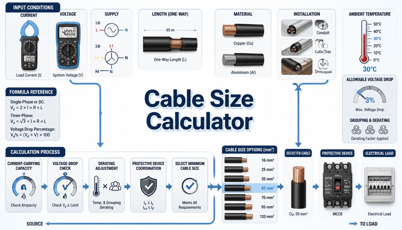
This guide explains the cable-sizing process, load-current and voltage-drop formulas, correction factors, practical examples, applications, limitations, and common selection mistakes. A calculated result should always be confirmed using the cable manufacturer’s data, applicable wiring regulations, current-carrying-capacity tables, and the actual installation method.
What Is a Cable Size Calculator?
A Cable Size Calculator is an electrical design tool used to estimate the required conductor size for carrying a specified load safely and with an acceptable voltage drop. Cable sizes are normally expressed in square millimetres (mm²) or American Wire Gauge (AWG), depending on the country and electrical standard being followed.
The calculator first determines or accepts the circuit design current. It then evaluates the conductor size against current-carrying capacity and voltage-drop requirements. An advanced calculation may also consider ambient temperature, cable grouping, thermal insulation, conductor material, insulation temperature rating, installation method, harmonics, and starting conditions.
The output is a preliminary cable recommendation rather than automatic approval for installation. Final selection must consider short-circuit withstand, protective-device coordination, disconnection requirements, terminal temperature limits, minimum permitted conductor size, mechanical strength, and local regulations.
How Does a Cable Size Calculator Work?
The calculator uses the entered electrical load to determine current, unless current is entered directly. It then estimates a conductor size that can carry the design current after relevant correction factors are applied. The proposed cable is also checked for voltage drop over the specified route length.
- Select AC single-phase, AC three-phase, or DC supply.
- Enter the load in amperes, watts, or kilowatts.
- Enter system voltage, power factor, and efficiency where required.
- Select copper or aluminium conductor material.
- Enter the one-way cable route length.
- Specify the allowable voltage drop.
- Apply installation and environmental correction factors.
- Compare the proposed size with approved ampacity tables.
A complete cable-sizing decision cannot be made from current alone. A conductor may have sufficient current capacity but still produce excessive voltage drop on a long circuit. Similarly, a cable that passes a voltage-drop calculation may require a larger size because of installation temperature, grouping, insulation, short-circuit duty, or protective-device requirements.
Step-by-Step Process
- Identify whether the circuit is DC, single-phase AC, or three-phase AC.
- Determine the design load current from equipment data or the appropriate current formula.
- Identify the supply voltage, power factor, efficiency, and operating duty.
- Select copper or aluminium as the conductor material.
- Confirm the cable insulation type and permitted operating temperature.
- Determine the installation method, such as conduit, cable tray, buried installation, or free air.
- Apply the relevant ambient-temperature, grouping, soil, and thermal-insulation factors.
- Select a preliminary size from an approved current-carrying-capacity table.
- Calculate voltage drop using the circuit length and load current.
- Check starting performance, short-circuit withstand, and protective-device coordination.
- Select the next suitable standard cable size when any requirement is not satisfied.
Cable Size Calculator Formula
Single-Phase Load Current
I = P ÷ (V × PF × η)
This formula determines the approximate current of a single-phase AC load when real input or output power, voltage, power factor, and efficiency are known. If the entered power is already electrical input power, efficiency should not be applied again.
Three-Phase Load Current
I = P ÷ (√3 × V × PF × η)
For a balanced three-phase load, V is normally the line-to-line voltage. When power is entered in kilowatts, multiply it by 1,000 before using the formula with voltage in volts.
DC Load Current
I = P ÷ V
For a basic DC load, current equals power divided by voltage. Converter efficiency and changing battery voltage may need to be included when sizing conductors for UPS, solar, battery, or DC control applications.
Basic Conductor Area from Current Density
S = I ÷ J
This gives a theoretical conductor area from a selected current density. However, current density is not a universal fixed value and should not replace approved current-carrying-capacity tables. Cable construction, insulation, installation, ambient conditions, and permitted conductor temperature all affect ampacity.
Single-Phase or DC Voltage Drop
Vd = (2 × ρ × L × I) ÷ S
This simplified resistive formula uses the one-way route length and includes both outgoing and return conductors through the factor 2. It is suitable for preliminary calculations where conductor reactance is negligible.
Three-Phase Voltage Drop
Vd = (√3 × ρ × L × I) ÷ S
This is a simplified balanced three-phase resistive formula. More complete AC calculations use cable resistance, reactance, and load power factor. Manufacturer voltage-drop values in mV/A/m are often more suitable for final design.
Voltage Drop Percentage
Vd% = (Vd ÷ V) × 100
The calculated voltage drop is divided by the nominal circuit voltage and multiplied by 100. The acceptable limit must be selected in accordance with the applicable wiring rules, equipment requirements, circuit type, and project specifications.
Corrected Cable Current Capacity
Iz,corrected = Iz,table × Ca × Cg × Ci × Cs
The tabulated cable capacity is multiplied by the applicable correction factors. The exact factors and their application depend on the governing standard and installation details. A factor should not be assumed or omitted without confirming whether it applies.
Formula Explanation
| Symbol | Description |
|---|---|
| I | Design or load current in amperes (A) |
| P | Real electrical power in watts (W) |
| V | Supply voltage in volts (V) |
| PF | Load power factor expressed as a decimal |
| η | Equipment efficiency expressed as a decimal |
| √3 | Three-phase constant, approximately 1.732 |
| S | Conductor cross-sectional area in mm² |
| J | Selected current density in A/mm² |
| Vd | Calculated voltage drop in volts |
| Vd% | Voltage drop as a percentage of supply voltage |
| ρ | Conductor resistivity in Ω·mm²/m at the selected temperature |
| L | One-way cable route length in metres |
| Iz, table | Tabulated current-carrying capacity of the cable |
| Ca | Ambient-temperature correction factor |
| Cg | Cable-grouping correction factor |
| Ci | Thermal-insulation correction factor where applicable |
| Cs | Additional installation or soil correction factor where applicable |
Interactive Cable Size Calculator
Use the calculator below to enter the electrical load, voltage, cable length, conductor material, and other required values to obtain a preliminary cable-size result.
⚡ Cable Size Calculator
Estimate a minimum conductor size from current, length, voltage drop, material, and system type.
Cable Size Result
Enter values and press Calculate.
DC / Single Phase: A = 2 × I × L × ρ × PF ÷ Vd
Three Phase: A = √3 × I × L × ρ × PF ÷ Vd
Example 1 – Cable Size for a Known Three-Phase Current
For a three-phase motor feeder carrying a known design current of 10 A, enter 10 A and select the installation conditions. The calculator recommends a conductor size based on the entered current.
Example 2 – Cable Size for a Known Single-Phase Current
For a single-phase load with a known design current of 16 A, enter 16 A and the applicable installation conditions. Review the suggested conductor size against local standards.
Example 3 – DC Cable Voltage Drop
Given:
- DC supply voltage = 24 V
- Load current = 10 A
- One-way cable length = 20 m
- Copper conductor area = 4 mm²
- Example copper resistivity = 0.0175 Ω·mm²/m
Vd = (2 × 0.0175 × 20 × 10) ÷ 4
Vd = 1.75 V
Vd% = (1.75 ÷ 24) × 100 ≈ 7.29%
The simplified calculation produces a voltage drop of approximately 1.75 V, or 7.29% of the 24 V supply. This may be excessive for sensitive DC equipment. A larger conductor, shorter route, higher distribution voltage, or local power supply may be needed. Final calculation should use conductor resistance at the expected operating temperature and the equipment’s permitted input-voltage range.
Example 4 – Three-Phase Cable Voltage Drop
Given:
- Three-phase voltage = 415 V
- Load current = 32 A
- One-way route length = 50 m
- Copper conductor area = 10 mm²
- Example copper resistivity = 0.0175 Ω·mm²/m
Vd = (1.732 × 0.0175 × 50 × 32) ÷ 10
Vd ≈ 4.85 V
Vd% = (4.85 ÷ 415) × 100 ≈ 1.17%
The simplified resistive voltage drop is approximately 4.85 V or 1.17%. A final AC calculation should use the manufacturer’s resistance and reactance data at the relevant temperature and account for load power factor. The cable must still pass ampacity, correction-factor, short-circuit, and protective-device checks.
Practical Field Considerations for Cable Sizing
In practical installations, cable size cannot be selected from load current alone. The same conductor may have different current-carrying capacities when installed in free air, inside conduit, in trunking, on a cable tray, surrounded by thermal insulation, or buried underground. Always select the correct reference installation method before using an ampacity table.
Ambient temperature and grouping can substantially reduce heat dissipation. Multiple loaded cables installed together may require a correction factor, while buried cables can be affected by soil temperature, thermal resistivity, burial depth, and spacing. The applicable factors must come from the governing standard or cable manufacturer’s verified data.
Motor and transformer circuits require attention to starting or inrush current. A cable may carry normal running current safely but still produce an unacceptable voltage dip during starting. Long motor feeders should therefore be checked under both normal running and starting conditions.
The cable must also withstand the prospective short-circuit current for the protective device’s clearing time. Neutral-conductor loading, harmonics, unbalanced phases, terminal temperature ratings, parallel conductors, and the required protective conductor must be evaluated separately where applicable.
Applications of a Cable Size Calculator
Industrial Applications
- Motor feeders and motor control centres
- Pumps, compressors, conveyors, and production machines
- Transformers, generators, and distribution panels
- Industrial heaters and high-power process loads
- Plant extensions and electrical retrofit projects
Electrical Applications
- Final circuits and distribution feeders
- Lighting and socket-outlet circuits
- Air-conditioning and ventilation systems
- DC supplies, UPS systems, and battery circuits
- Solar and renewable-energy installations
Automation Applications
- PLC control-panel incoming feeders
- Variable-frequency-drive input and motor cables
- Remote sensors and 24 V DC control circuits
- Solenoid valves and field-actuator supplies
- SCADA and remote-I/O panel power distribution
Advantages of a Cable Size Calculator
- Reduces repetitive load-current calculations.
- Helps compare copper and aluminium conductors.
- Supports single-phase, three-phase, and DC circuits.
- Identifies voltage-drop problems on long cable routes.
- Assists preliminary material and project-cost estimates.
- Encourages consideration of installation and derating factors.
- Helps students understand cable-selection principles.
Limitations
- Results depend on correct load and installation information.
- Current-density calculations cannot replace approved ampacity tables.
- Actual cable resistance changes with conductor temperature.
- Simplified voltage-drop formulas may exclude cable reactance.
- Motor-starting and transformer-inrush conditions require additional checks.
- Short-circuit withstand and protective-device coordination must be verified separately.
- Different countries and projects may apply different wiring requirements.
- The result does not replace manufacturer data or professional engineering judgment.
Common Mistakes
- Selecting cable size only from the load current.
- Ignoring route length and voltage drop.
- Using the wrong single-phase or three-phase formula.
- Confusing motor output power with electrical input power.
- Ignoring ambient-temperature and grouping factors.
- Using free-air ampacity for a cable installed in conduit.
- Ignoring conductor operating temperature in voltage-drop calculations.
- Forgetting motor-starting voltage drop.
- Failing to check short-circuit withstand.
- Selecting a protective device without coordinating it with the conductor.
Once the conductor size is selected, validate cable-run losses with the Voltage Drop Calculator. For motor feeders, obtain the design amperes from the Motor Current Calculator.
Frequently Asked Questions
What is a Cable Size Calculator?
A Cable Size Calculator estimates a suitable conductor size using load current, voltage, phase type, cable length, conductor material, voltage drop, and installation conditions.
Can cable size be selected from current alone?
No. Current capacity is one requirement, but voltage drop, installation method, ambient temperature, grouping, short-circuit withstand, and protective-device coordination must also be checked.
Does a longer cable require a larger conductor?
It may. Increasing circuit length increases conductor resistance and voltage drop, so a larger size may be required even when the smaller cable has sufficient current capacity.
What is the difference between copper and aluminium cable?
Copper has lower resistivity than aluminium and generally requires a smaller cross-sectional area for the same electrical performance. Aluminium is lighter but requires compatible terminals and installation practices.
What correction factors affect cable ampacity?
Relevant factors may include ambient temperature, grouping, thermal insulation, soil thermal resistivity, burial conditions, installation method, and the number of loaded conductors.
Should motor cables be sized for starting current?
Normal ampacity selection is based on the applicable motor-circuit requirements, but the cable should also be checked to ensure that starting current does not cause unacceptable voltage drop or starting performance.
Can I use a cable calculator for DC circuits?
Yes. DC cable sizing is especially sensitive to voltage drop at low voltages. The outgoing and return conductor lengths must both be included in the resistance calculation.
Should the calculator result be verified before installation?
Yes. Confirm the result using applicable wiring regulations, approved ampacity tables, manufacturer data, installation conditions, voltage-drop limits, and protection requirements.
Related Electrical Calculators
Helpful Electrical Engineering Resources
Conclusion
A Cable Size Calculator provides a structured starting point for selecting conductors based on circuit current, voltage, phase type, route length, conductor material, and voltage drop. It can help identify whether a proposed cable requires further evaluation or whether a larger standard size may be necessary.
A final cable selection must satisfy more than the basic current calculation. Current-carrying capacity after correction factors, voltage drop, starting performance, short-circuit withstand, protective-device coordination, terminal ratings, installation method, and local regulations must all be considered.
Tech Volt Lab provides practical electrical and automation calculators for engineers, electricians, PLC technicians, maintenance professionals, and students. Use the calculated result as a preliminary engineering reference and verify it against the applicable standard, manufacturer documentation, and actual site conditions before installation.
Explore More Engineering Calculators
Discover more free electrical and automation calculators designed for electricians, PLC programmers, maintenance technicians, and engineers.