 Tech Volt Lab Automation | PLC | SCADA | Electrical | Electronics

Related Articles

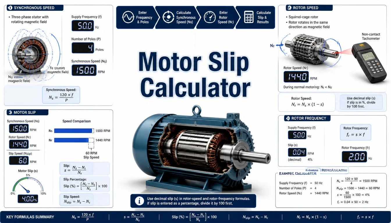
A Motor Slip Calculator determines the difference between the synchronous speed of an induction motor’s rotating magnetic field and its actual rotor speed. It calculates synchronous speed, slip speed in RPM, slip as a decimal, slip percentage, and rotor electrical frequency from supply frequency, pole count, and measured rotor speed.
Slip is necessary for a conventional induction motor to produce torque. If the rotor operated at the same speed as the rotating magnetic field, there would be no relative motion between the field and rotor conductors under ideal steady-state conditions. Without this relative motion, rotor voltage and current would not be induced, and electromagnetic torque could not be maintained.
Electricians, maintenance technicians, engineers, motor-repair professionals, automation specialists, and students can use this calculator to evaluate motor speed information. Accurate results require the actual motor supply frequency, the correct number of poles, and a reliable rotor-speed measurement taken under a known operating condition.
What Is a Motor Slip Calculator?
A Motor Slip Calculator compares the actual rotor speed of an induction motor with its calculated synchronous speed. Synchronous speed is determined by the electrical frequency applied to the stator and the number of magnetic poles in the motor.
The actual rotor speed is normally slightly lower than synchronous speed while a standard induction motor is operating in motoring mode. The difference between these two speeds is called slip speed. Slip can be expressed in revolutions per minute, as a decimal ratio, or as a percentage of synchronous speed.
For example, the synchronous speed of a four-pole motor supplied at 50 Hz is 1,500 RPM. If its measured rotor speed is 1,455 RPM, the slip speed is 45 RPM, and the slip percentage is 3%. The Motor Slip Calculator performs these calculations automatically and helps reduce formula and unit-conversion errors.
Motor slip is different from motor efficiency, power factor, speed regulation, and mechanical losses. Although these characteristics may influence motor performance, each represents a different electrical or mechanical relationship and should be evaluated separately.
How Does a Motor Slip Calculator Work?
The calculator first determines synchronous speed from the supply frequency and motor pole count. It then compares that value with the measured or nameplate rotor speed. The difference is used to calculate slip RPM and slip percentage.
- Enter the electrical frequency supplied to the motor.
- Enter the motor’s number of magnetic poles.
- Enter the measured or rated rotor speed in RPM.
- Calculate the synchronous speed of the rotating magnetic field.
- Subtract rotor speed from synchronous speed to find slip RPM.
- Divide slip RPM by synchronous speed to obtain the slip ratio.
- Multiply the slip ratio by 100 to express the result as a percentage.
If the motor is controlled by a variable frequency drive, use the drive’s actual output frequency at the measurement point rather than automatically entering the normal utility frequency. A VFD can change the motor’s synchronous speed by changing its output frequency.
Step-by-Step Process
- Confirm that the machine uses an induction motor.
- Identify the motor’s number of poles from its documentation or design information.
- Determine the actual supply frequency in hertz.
- Measure the rotor or shaft speed with a suitable tachometer, encoder, or speed sensor.
- Record the motor’s operating condition, including whether it is unloaded, partially loaded, or fully loaded.
- Enter the frequency, pole count, and rotor speed into the calculator.
- Calculate synchronous speed, slip speed, and slip percentage.
- Compare the result with the motor nameplate, manufacturer data, and previous measurements.
- Investigate unexpected changes using electrical and mechanical tests rather than relying on slip alone.
Motor Slip Calculator Formula
Motor slip is calculated from synchronous speed and actual rotor speed. The principal slip percentage formula is:
s% = [(Ns − Nr) ÷ Ns] × 100
The synchronous speed must be calculated before slip can be determined when it is not already known. Synchronous speed depends on frequency and the number of poles.
Synchronous Speed Formula
Ns = (120 × f) ÷ P
This formula calculates the speed of the stator’s rotating magnetic field in revolutions per minute. A higher supply frequency increases synchronous speed, while a higher pole count reduces synchronous speed.
Slip Speed Formula
Nslip = Ns − Nr
Slip speed is the numerical difference between synchronous speed and actual rotor speed. It is expressed in RPM and should not be confused with the dimensionless slip ratio.
Slip Ratio Formula
s = (Ns − Nr) ÷ Ns
s% = s × 100
A slip ratio of 0.03 is equal to 3%. Always confirm whether a calculator input requires a decimal ratio or a percentage. Entering 3 instead of 0.03 in a decimal field would produce an incorrect result.
Rotor Speed from Slip
Nr = Ns × (1 − s)
When slip is entered as a percentage, the formula becomes:
Nr = Ns × [1 − (s% ÷ 100)]
This variation calculates the estimated rotor speed when synchronous speed and motor slip are known.
Slip Frequency Formula
fr = s × f
The rotor electrical frequency, also called slip frequency, is the stator supply frequency multiplied by the slip ratio. At standstill, slip equals 1 and rotor frequency equals the applied stator frequency. As the rotor approaches synchronous speed, slip frequency decreases.
Motor Pole and Frequency Formulas
P = (120 × f) ÷ Ns
f = (Ns × P) ÷ 120
The calculated pole count should correspond to a physically plausible even integer, such as 2, 4, 6, or 8 poles. Do not calculate pole count directly from loaded shaft speed without first allowing for slip. For example, a motor operating close to 1,450 RPM on a 50 Hz supply is normally a four-pole motor with a 1,500 RPM synchronous speed.
Formula Explanation
| Symbol | Description |
|---|---|
| Ns | Synchronous speed of the rotating magnetic field in RPM |
| Nr | Actual rotor or shaft speed in RPM |
| Nslip | Difference between synchronous and rotor speed in RPM |
| s | Motor slip expressed as a decimal ratio |
| s% | Motor slip expressed as a percentage |
| f | Electrical supply or drive output frequency in hertz |
| fr | Rotor electrical frequency or slip frequency in hertz |
| P | Total number of magnetic poles in the motor |
| 120 | Conversion constant for frequency, pole count, and RPM |
| RPM | Revolutions per minute |
At standstill, rotor speed is zero, and slip is 100%. During normal motoring operation, the rotor accelerates toward synchronous speed but remains below it. If measured rotor speed is higher than synchronous speed, the formula produces negative slip, which may indicate regenerative operation, an incorrect pole or frequency entry, or a speed-measurement problem.
Interactive Motor Slip Calculator
Enter the motor frequency, pole count, and actual rotor speed to calculate synchronous speed and slip results.
Calculate synchronous speed, motor slip, and rotor frequency. Enter values and press Calculate.⚡ Motor Slip Calculator
Motor Slip Result
Ns = 120f ÷ poles
Slip = (Ns − Nr) ÷ Ns × 100
Rotor frequency = slip fraction × supply frequency
Example 1 – Calculate Slip for a 50 Hz Motor
A four-pole induction motor is supplied at 50 Hz, and its measured rotor speed is 1,450 RPM. Calculate synchronous speed, slip speed, slip percentage, and slip frequency.
Given: f = 50 Hz, P = 4 and Nr = 1,450 RPM
Synchronous speed: Ns = (120 × 50) ÷ 4 = 1,500 RPM
Slip speed: Nslip = 1,500 − 1,450 = 50 RPM
Slip percentage: s% = (50 ÷ 1,500) × 100 = 3.33%
Slip frequency: fr = 0.0333 × 50 ≈ 1.67 Hz
Final result: The synchronous speed is 1,500 RPM, slip speed is 50 RPM, motor slip is approximately 3.33%, and rotor electrical frequency is approximately 1.67 Hz.
Example 2 – Calculate Slip for a 60 Hz Motor
A six-pole induction motor operates from a 60 Hz supply, and its shaft speed is 1,164 RPM. Calculate its motor slip.
Given: f = 60 Hz, P = 6 and Nr = 1,164 RPM
Synchronous speed: Ns = (120 × 60) ÷ 6 = 1,200 RPM
Slip speed: Nslip = 1,200 − 1,164 = 36 RPM
Slip percentage: s% = (36 ÷ 1,200) × 100 = 3%
Slip frequency: fr = 0.03 × 60 = 1.8 Hz
Final result: The motor has a synchronous speed of 1,200 RPM, a slip speed of 36 RPM, a slip percentage of 3%, and a slip frequency of 1.8 Hz.
Example 3 – Compare Motor Slip at Different Loads
A four-pole motor supplied at 50 Hz operates at 1,492 RPM with very little mechanical load. Its speed decreases to 1,460 RPM when the process load is applied. Compare the two slip values.
Synchronous speed: Ns = (120 × 50) ÷ 4 = 1,500 RPM
Light-load slip: s% = [(1,500 − 1,492) ÷ 1,500] × 100 ≈ 0.53%
Loaded slip: s% = [(1,500 − 1,460) ÷ 1,500] × 100 ≈ 2.67%
Final result: Slip increases from approximately 0.53% at light load to 2.67% under the applied load. An increase in slip with increasing load is a normal characteristic of an induction motor. However, assess any large or unexpected change alongside current, voltage balance, mechanical load, temperature, vibration, and manufacturer data.
Practical Field Considerations for Motor Slip
A motor nameplate normally shows rated or full-load speed rather than synchronous speed. A four-pole, 50 Hz induction motor may therefore have a nameplate speed such as 1,450 or 1,470 RPM instead of 1,500 RPM. The difference allows the motor to develop its rated torque.
Slip changes with mechanical load. A lightly loaded motor generally operates closer to synchronous speed, while a loaded motor slows slightly and develops additional torque. Therefore, compare speed measurements only when operating conditions are reasonably similar.
Use the actual frequency applied to the motor. For a directly connected motor, this may be close to the nominal 50 or 60 Hz supply frequency. For a VFD-controlled motor, the output frequency can vary continuously, so assuming the nominal mains frequency may produce an incorrect synchronous speed.
Accurate shaft-speed measurement is also important. A handheld optical or contact tachometer may be suitable for periodic testing, while an encoder or permanently installed speed sensor may be preferred for continuous monitoring. Follow safe working procedures around rotating shafts, couplings, belts, fans, and other moving equipment.
High slip alone does not identify a specific motor fault. Possible causes can include excessive mechanical load, low or unbalanced voltage, incorrect supply frequency, rotor damage, speed-measurement error, unsuitable drive settings, or selection of the wrong motor data. Confirm the condition with appropriate electrical and mechanical tests.
Applications of a Motor Slip Calculator
Industrial Motor Applications
- Checking induction motor speed under operating load.
- Comparing measured speed with nameplate information.
- Reviewing motors used for pumps, fans, conveyors, and compressors.
- Supporting preliminary motor-loading investigations.
Maintenance and Troubleshooting Applications
- Trending shaft speed and slip over time.
- Identifying unexpected speed changes at similar loads.
- Comparing motor behavior before and after maintenance.
- Supporting electrical and mechanical fault investigations.
Automation and VFD Applications
- Comparing encoder feedback with calculated synchronous speed.
- Reviewing speed changes as drive output frequency changes.
- Checking motor and machine-speed relationships.
- Supporting commissioning and drive-parameter verification.
Educational Applications
- Understanding induction motor operating principles.
- Calculating synchronous speed from frequency and pole count.
- Comparing slip RPM, slip ratio, and slip percentage.
- Studying rotor frequency at different motor speeds.
Advantages of a Motor Slip Calculator
- Calculates synchronous speed quickly.
- Converts speed difference into a slip percentage.
- Calculates slip speed from synchronous and measured rotor speeds.
- Determines rotor electrical or slip frequency.
- Reduces repetitive manual calculations.
- Helps compare motors with different frequencies and pole counts.
- Supports commissioning, maintenance, and educational work.
- Provides results in both RPM and percentage formats.
Limitations
- The standard formulas are intended for induction motors.
- Results depend on accurate frequency, pole count, and rotor-speed inputs.
- A calculated slip value does not identify the exact cause of a motor problem.
- Motor slip changes with mechanical load and operating temperature.
- Nameplate speed may not equal speed under the current field condition.
- Nominal mains frequency should not replace actual VFD output frequency.
- Transient acceleration and starting conditions require additional analysis.
- The calculator does not replace manufacturer data, measurements, or professional diagnosis.
Common Mistakes
- Using rotor speed as synchronous speed.
- Entering pole pairs instead of the total number of poles.
- Using 50 or 60 Hz for a motor operating at a different VFD output frequency.
- Entering percentage slip as a decimal without conversion.
- Dividing slip speed by rotor speed instead of synchronous speed.
- Comparing speed measurements taken under very different loads.
- Assuming the nameplate RPM is the motor’s synchronous speed.
- Using the calculation for a synchronous motor without considering its operating principle.
- Treating negative slip as automatically impossible without checking for regeneration.
- Diagnosing a motor fault from slip alone.
Compare calculated rotor speed with the RPM Calculator and estimate mechanical output using the Torque Calculator.
Frequently Asked Questions
What is a Motor Slip Calculator?
It calculates the difference between induction motor synchronous speed and actual rotor speed. The result can be expressed as slip RPM, a decimal ratio, or a percentage.
What is the motor slip formula?
The percentage formula is s% = [(Ns − Nr) ÷ Ns] × 100, where Ns is synchronous speed, and Nr is actual rotor speed.
Why is slip required in an induction motor?
Relative motion between the rotating stator field and the rotor is required to induce rotor voltage and current and allow the motor to produce torque.
Is nameplate speed the same as synchronous speed?
No. An induction motor nameplate normally shows its rated operating speed, which is lower than synchronous speed because of slip.
Does motor slip increase with load?
Motor slip generally increases as mechanical load increases because the rotor slows slightly relative to the rotating magnetic field to develop additional torque.
What happens to slip at synchronous speed?
At synchronous speed, slip is zero. A conventional induction motor cannot maintain normal motoring torque at exactly zero slip under ideal steady-state conditions.
Which frequency should I use for a VFD motor?
Use the actual VFD output frequency at the operating point being evaluated, not automatically the nominal utility-supply frequency.
Does high motor slip always mean the motor is faulty?
No. Slip depends on load and motor design. Unexpectedly high slip should be investigated with current, voltage, load, temperature, vibration, speed, and manufacturer information.
Related Tech Volt Lab Resources
Helpful Electrical Engineering Resources
Final Thoughts
A Motor Slip Calculator determines synchronous speed and compares it with actual induction motor rotor speed. It can calculate slip speed in RPM, slip ratio, slip percentage, and rotor electrical frequency.
These calculations support motor commissioning, preventive maintenance, troubleshooting, drive assessments, machine-speed reviews, and electrical education. The most reliable analysis uses accurate speed and frequency measurements recorded under a known and repeatable load condition.
Use the Motor Slip Calculator from Tech Volt Lab as a practical calculation and comparison tool. For important maintenance or design decisions, confirm the result using the motor nameplate, manufacturer performance data, drive information, electrical measurements, mechanical-load checks, and suitable professional judgment.
Explore More Engineering Calculators
Discover more free electrical and automation calculators designed for electricians, PLC programmers, maintenance technicians, and engineers.
View All Calculators