 Tech Volt Lab Automation | PLC | SCADA | Electrical | Electronics

Related Articles

An Inductor Calculator calculates key electrical values for inductors, including inductive reactance, stored magnetic energy, the RL time constant, equivalent series inductance, and equivalent parallel inductance. Electronics engineers, electricians, automation technicians, maintenance professionals, circuit designers, and students can use it to evaluate inductors in AC circuits, filters, power supplies, relay coils, and control systems. An inductor opposes changes in current and stores energy in its magnetic field. Its behavior depends on inductance, frequency, current, winding resistance, core material, temperature, and circuit arrangement.
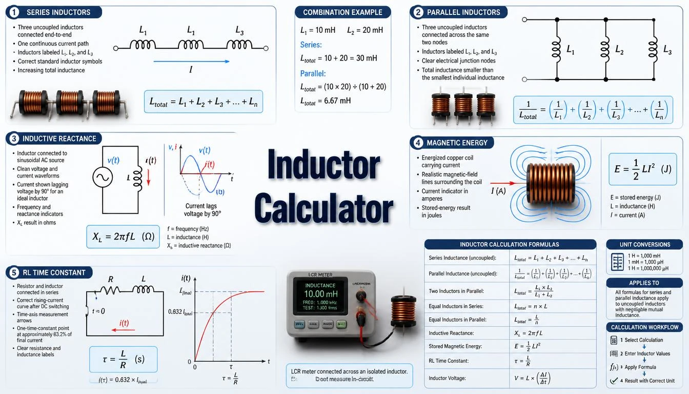
Use the correct formula and units because millihenries, microhenries, amperes, ohms, and hertz cannot be used interchangeably without conversion.
This guide explains the main inductor formulas, series and parallel connections, inductive reactance, stored energy, RL circuit timing, numerical examples, practical applications, and real-component limitations. The calculated values support circuit analysis and preliminary selection, but final component choice must also consider manufacturer ratings and actual operating conditions.
What Is an Inductor Calculator?
An Inductor Calculator is an engineering tool that applies different formulas according to the selected calculation mode. It can calculate the opposition an inductor presents to AC, the energy stored at a specified current, the charging response of an RL circuit, or the combined inductance of multiple inductors.
Common inputs include inductance in henries, millihenries, or microhenries; frequency in hertz or kilohertz; current in amperes; and resistance in ohms. For series and parallel calculations, the user enters two or more individual inductance values. The output may be expressed in henries, reactance in ohms, energy in joules, or time in seconds.
The calculator can support preliminary analysis of power converters, filters, oscillators, transformers, motor-control circuits, electromagnetic devices, and industrial control panels. A mathematical result is not automatically a suitable commercial inductor rating. Saturation current, RMS current, DC resistance, temperature rise, core loss, self-resonant frequency, tolerance, insulation, and physical size require separate verification.
How Does an Inductor Calculator Work?
The calculator first identifies the required calculation and converts the entered values into base SI units. Inductance is converted to henries, frequency to hertz, resistance to ohms, and current to amperes. It then applies the appropriate inductor equation and converts the final result into a readable unit.
- Select inductive reactance, stored energy, time constant, series, or parallel calculation.
- Enter the known inductance, frequency, current, or resistance.
- Select the correct unit for each entered value.
- Add individual inductance values when calculating a network.
- Press Calculate and review the result with its unit.
- Compare the result with manufacturer specifications and circuit requirements.
The calculation represents the selected mathematical model. It does not replace equipment nameplates, component datasheets, applicable electrical standards, local electrical codes, laboratory measurements, or professional engineering judgment.
Step-by-Step Process
- Select the required inductor calculation type.
- Enter the primary inductance value.
- Select H, mH, or µH as the inductance unit.
- Enter frequency, current, resistance, or additional inductors as required.
- Check that frequency is entered in the correct Hz, kHz, or MHz unit.
- Confirm conversions before performing a manual comparison.
- Press Calculate and review the result.
- Check whether the result represents H, Ω, J, s, or another displayed unit.
- Compare critical results with the component datasheet and operating conditions.
Inductor Calculator Formula
Inductance describes the relationship between the voltage across an ideal inductor and the rate at which current changes:
v = L × (di ÷ dt)
L = v ÷ (di ÷ dt)
In these formulas, v is the instantaneous voltage in volts, L is the inductance in henries, and di/dt is the rate of current change in amperes per second. The polarity of induced voltage follows the selected reference direction and Lenz’s law.
Inductive Reactance Formula
XL = 2πfL
Inductive reactance is the opposition an ideal inductor presents to sinusoidal alternating current. Use frequency f in hertz and inductance L in henries to obtain XL in ohms. Inductive reactance increases when frequency or inductance increases.
L = XL ÷ (2πf)
f = XL ÷ (2πL)
For an ideal inductor, complex impedance is written as ZL = jXL. A real inductor also has winding resistance and frequency-dependent losses, so its total impedance is not purely imaginary.
Energy Stored in an Inductor
E = ½ × L × I²
This formula calculates the magnetic energy stored in an ideal linear inductor. Use inductance in henries and current in amperes to obtain energy in joules. Energy increases directly with inductance and with the square of current.
L = 2E ÷ I²
I = √(2E ÷ L)
The simple energy formula assumes that inductance remains constant at the selected current. Magnetic-core inductors may lose inductance as they approach saturation, so the actual stored energy must be evaluated using manufacturer curves where necessary.
RL Time Constant Formula
τ = L ÷ R
The RL time constant indicates how quickly current changes in a simple first-order series RL circuit after a DC voltage step. Use inductance in henries and total series resistance in ohms to obtain the time constant in seconds.
i(t) = Ifinal × [1 − e−t/τ]
Ifinal = V ÷ R
During current rise, an ideal first-order RL circuit reaches approximately 63.2% of its final current after one time constant. After about five time constants, it is close to its final steady-state value. Coil resistance and external circuit resistance must both be included where applicable.
Series Inductors Formula
LT = L1 + L2 + … + Ln
The total inductance of uncoupled inductors connected in series is the sum of the individual values. This formula assumes that mutual magnetic coupling between the inductors is negligible.
Parallel Inductors Formula
1 ÷ LT = 1 ÷ L1 + 1 ÷ L2 + … + 1 ÷ Ln
For two uncoupled inductors in parallel, the formula can be simplified:
LT = (L1 × L2) ÷ (L1 + L2)
The equivalent parallel inductance is lower than the smallest individual inductance. The calculation assumes ideal inductors with no mutual coupling. Current sharing between real parallel inductors may be affected by tolerance, winding resistance, temperature, and magnetic characteristics.
Air-Core Solenoid Approximation
L = μ × N² × A ÷ l
This simplified expression estimates the inductance of a long solenoid with a reasonably uniform magnetic field. Here, μ is magnetic permeability in H/m, N is the number of turns, A is the coil cross-sectional area in square metres, and l is the magnetic path length in metres.
Short coils, gapped cores, bobbin geometry, fringing, leakage flux, winding spacing, and nonlinear magnetic materials require more detailed models or manufacturer design tools. A basic geometry calculation should not be treated as a guaranteed manufactured inductance.
Formula Explanation
| Symbol | Description |
|---|---|
| L | Inductance in henries (H) |
| LT | Total equivalent inductance in henries (H) |
| L1 to Ln | Individual inductance values in matching units |
| XL | Inductive reactance in ohms (Ω) |
| ZL | Complex impedance of an ideal inductor in ohms (Ω) |
| f | Frequency in hertz (Hz) |
| E | Stored magnetic energy in joules (J) |
| I | Current through the inductor in amperes (A) |
| Ifinal | Final steady-state current in amperes (A) |
| V | Applied DC step voltage in volts (V) |
| R | Total series resistance in ohms (Ω) |
| τ | RL circuit time constant in seconds (s) |
| t | Elapsed time in seconds (s) |
| v | Instantaneous inductor voltage in volts (V) |
| di/dt | Rate of current change in amperes per second (A/s) |
| j | Imaginary operator, where j² = −1 |
| e | Base of the natural logarithm |
| μ | Magnetic permeability in henries per metre (H/m) |
| N | Number of coil turns |
| A | Coil cross-sectional area in square metres (m²) |
| l | Magnetic path or solenoid length in metres (m) |
| π | Mathematical constant, approximately 3.14159 |
Interactive Inductor Calculator
Use the calculator below to enter the required values and obtain the calculated engineering result.
Calculate inductive energy, RL time constant, or inductance from reactance. Enter values and press Calculate.⚡ Inductor Calculator
Inductor Result
Energy E = ½LI²
RL time constant τ = L ÷ R
L = XL ÷ (2πf)
Example 1 – Calculate Inductance from Reactance
Select Inductance from Reactance, then enter an inductive reactance of 62.83 Ω and a frequency of 1,000 Hz.
Inductance: L = XL ÷ (2πf) = 62.83 ÷ (2π × 1,000) = 0.010 H
Final result: The calculator returns approximately 10 mH.
Example 2 – Calculate Stored Inductor Energy
A 10 mH power inductor carries 3 A. Convert the inductance to 0.010 H and calculate the ideal stored magnetic energy.
Given: L = 0.010 H and I = 3 A
Formula: E = ½ × L × I²
Calculation: E = 0.5 × 0.010 × 3²
Final result: E = 0.045 J or 45 mJ
The ideal stored energy is 45 millijoules. Before selecting the component, verify that 3 A is within the manufacturer’s saturation-current and temperature-rise ratings under the intended switching frequency and ambient conditions.
Example 3 – Calculate an RL Time Constant
A series RL circuit contains a 200 mH inductor and 40 Ω total resistance. Convert 200 mH to 0.200 H.
Given: L = 0.200 H and R = 40 Ω
Formula: τ = L ÷ R
Calculation: τ = 0.200 ÷ 40 = 0.005 s
Final result: τ = 5 ms
The current reaches approximately 63.2% of its final value after 5 ms in the ideal first-order model. It will be close to its final value after approximately 25 ms, which equals five time constants.
Example 4 – Find Inductance at 50 Hz
Select Inductance from Reactance, then enter 31.42 Ω and 50 Hz.
Inductance: L = 31.42 ÷ (2π × 50) = 0.100 H
Final result: The required inductance is approximately 100 mH.
Practical Field Considerations for Inductor Calculations
The inductance printed on a component is normally a nominal value measured under defined test conditions. Actual inductance can vary because of manufacturing tolerance, test frequency, signal level, temperature, DC bias, magnetic core characteristics, and mechanical construction.
Power-inductor selection requires more than an inductance value. Check the saturation-current rating, temperature-rise current, DC resistance, core loss, operating temperature range, switching frequency, package dimensions, and allowable temperature rise. The lower of the applicable current limits may control the final selection.
An inductor can produce a high voltage when its current is interrupted because it opposes rapid current change. Relay, contactor, and solenoid circuits commonly require a suitable flyback diode, RC snubber, transient voltage suppressor, or other suppression arrangement. The correct method depends on AC or DC operation, release-time requirements, switching device ratings, and manufacturer guidance.
At high frequencies, winding capacitance can interact with inductance and create self-resonance. Above the self-resonant frequency, the component may no longer behave primarily as an inductor. Manufacturer impedance and frequency curves should therefore be checked for RF filters, switching converters, and high-speed signal circuits.
Inductors placed close together can become magnetically coupled. Their total inductance may then depend on mutual inductance, winding orientation, spacing, and whether the magnetic fields aid or oppose one another. The ordinary uncoupled series and parallel formulas are not sufficient for intentionally coupled windings or transformers.
Applications of an Inductor Calculator
Power Electronics Applications
- Reviewing inductors for buck, boost, and other switching converters.
- Estimating stored energy at a specified peak current.
- Comparing inductance and reactance at switching frequencies.
- Supporting preliminary input and output filter analysis.
Industrial Automation Applications
- Evaluating relay, contactor, valve, and solenoid coils.
- Estimating RL timing in electromagnetic control circuits.
- Reviewing filter chokes in PLC and control-panel power supplies.
- Supporting flyback and transient-suppression calculations.
Electronics Applications
- Designing passive filters and resonant circuits.
- Calculating inductive reactance in audio and signal circuits.
- Combining multiple inductors in series or parallel.
- Comparing components for RF and electromagnetic interference filtering.
Educational Applications
- Learning the relationship between voltage and changing current.
- Studying inductive reactance and phase relationships.
- Understanding magnetic energy storage.
- Practising series, parallel, and RL circuit calculations.
Advantages of an Inductor Calculator
- Reduces repetitive manual calculations.
- Supports common H, mH, and µH conversions.
- Calculates reactance at different frequencies.
- Estimates magnetic energy at a selected current.
- Calculates RL time constants.
- Combines uncoupled inductors in series or parallel.
- Supports preliminary design comparisons and troubleshooting.
- Helps students understand inductor formulas.
Limitations
- Results depend on correct inductance, frequency, current, resistance, and units.
- Ideal formulas may exclude winding resistance, core loss, and parasitic capacitance.
- Inductance may decrease when DC approaches magnetic saturation.
- Temperature and frequency can change actual component behavior.
- Uncoupled series and parallel formulas do not account for mutual inductance.
- Steady-state calculations do not automatically include switching transients.
- Calculated energy does not establish a complete power-inductor rating.
- The calculator does not replace manufacturer data or professional judgment.
Common Mistakes
- Entering millihenries directly into a formula requiring henries.
- Confusing inductance in henries with reactance in ohms.
- Ignoring the operating frequency when calculating reactance.
- Using reactance alone as the complete impedance of a real coil.
- Ignoring winding resistance when calculating an RL time constant.
- Using RMS current instead of peak current when the energy calculation requires peak current.
- Applying uncoupled formulas to magnetically coupled coils.
- Ignoring saturation current, temperature rise, and core loss.
- Operating above the component’s self-resonant frequency without checking its characteristics.
- Treating a calculated value as the final component selection.
For AC applications, verify operating frequency with the Frequency Calculator and winding current with the Current Calculator.
Frequently Asked Questions
What is an Inductor Calculator?
It calculates values associated with inductors, including reactance, stored energy, RL time constant, and equivalent series or parallel inductance.
What is the unit of inductance?
The SI unit of inductance is the henry. Practical components are commonly rated in henries, millihenries, microhenries, or nanohenries.
What is the inductive reactance formula?
The formula is XL = 2πfL, where frequency is in hertz and inductance is in henries.
How much energy does an inductor store?
For an ideal linear inductor, stored energy is E = ½LI², with inductance in henries and current in amperes.
How are inductors added in series?
Uncoupled series inductors are added directly. The total inductance equals the sum of the individual values.
How are inductors calculated in parallel?
For uncoupled parallel inductors, add the reciprocals of their inductances and take the reciprocal of the total.
What is the RL time constant?
The time constant is τ = L/R. It describes how quickly current rises or falls in a basic first-order RL circuit.
Can calculated inductance be used for final component selection?
No. Also verify current ratings, saturation, DC resistance, temperature rise, core loss, tolerance, self-resonant frequency, and manufacturer data.
Related Tech Volt Lab Resources
Helpful Electrical Engineering Resources
Final Thoughts
An Inductor Calculator determines inductive reactance, stored magnetic energy, RL time constant, and equivalent inductance for series or parallel connections. These calculations help explain how an inductor responds to changing current, frequency, resistance, and circuit arrangement.
The results support power-supply design, filter analysis, relay and solenoid circuits, industrial control systems, electronics troubleshooting, and engineering education. Practical behavior may differ because of winding resistance, magnetic saturation, core loss, temperature, tolerance, coupling, and parasitic capacitance.
Use the Inductor Calculator from Tech Volt Lab as a practical calculation and comparison tool. Verify important results using component datasheets, manufacturer curves, suitable measurements, applicable requirements, and a complete engineering assessment before making final circuit or equipment decisions.
Explore More Engineering Calculators
Discover more free electrical and automation calculators designed for electricians, PLC programmers, maintenance technicians, and engineers.
View All Calculators