 Tech Volt Lab Automation | PLC | SCADA | Electrical | Electronics

Related Articles

A PLC troubleshooting checklist should help you find the first failed condition without creating a second fault. A stopped machine can be caused by lost control power, an open safety circuit, a failed sensor, damaged wiring, a disabled output, a communication error, an interlock, or incorrect program data. This guide gives technicians and engineers a safe, repeatable sequence for investigating common PLC-controlled machine problems.
Safety warning: Follow the site’s lockout/tagout procedure, electrical safety rules, machine risk assessment, and manufacturer documentation. Only qualified personnel should test energized equipment. Never bypass an emergency stop, guard switch, overload, safety relay, or other protective device to force a machine to run.
PLC Troubleshooting Checklist: 10 Essential Steps
| Step | Check | Evidence to Record | Safe Action |
|---|---|---|---|
| 1 | Make the machine safe | Isolation status and permit | Apply the approved lockout/tagout procedure. |
| 2 | Confirm the reported fault | Time, alarm, operating mode and last action | Observe symptoms without forcing outputs. |
| 3 | Check PLC and control power | Measured voltage and LED states | Correct fuse, supply, neutral or grounding faults first. |
| 4 | Read CPU diagnostics | RUN/STOP/ERR LEDs and diagnostic message | Record the code before clearing or restarting. |
| 5 | Verify safety and permissives | Open interlock, trip or missing ready signal | Find the first false condition in the sequence. |
| 6 | Compare physical inputs with online status | Field voltage, input LED and software bit | Test sensor supply, polarity, wiring and common terminals. |
| 7 | Trace the program logic | First open contact, timer or sequence condition | Monitor only. Avoid online edits during fault finding. |
| 8 | Check output command and field circuit | Logic state, output LED, terminal voltage and load state | Isolate before checking coils, relays or wiring resistance. |
| 9 | Check communication and analog values | Node status, error counters, raw value and scaling | Verify cable, address, baud rate, protocol and range. |
| 10 | Restore and document | Root cause, repair, test result and backup reference | Remove temporary tests and restart under control. |
1. Define the Fault Before Opening the Program
Ask what stopped, when it stopped, which product or recipe was running, whether maintenance recently changed anything, and which alarm appeared first. A clear fault statement such as “conveyor output is commanded but the contactor does not energize” is more useful than “the PLC is not working.” Record the machine mode, cycle step, HMI message, and any intermittent behavior.
2. Check Power, Grounding, and PLC Indicators
Inspect the control transformer or 24 V DC power supply, protective devices, loose terminals, earth connections, and PLC rack power. Use the Transformer Calculator when you need to verify expected primary or secondary current. Measure voltage at the PLC and field terminals with an appropriate instrument. A power supply may show 24 V with no load but collapse when relays, valves, or modules energize. Compare PWR, RUN, STOP, ERR, battery, I/O, and communication LEDs with the manufacturer’s manual.
3. Read Diagnostics Before Resetting
Connect with the correct programming software and read the CPU diagnostic buffer, fault table, module status, and network diagnostics. Save the exact error code, module address, timestamp, and event sequence before clearing anything. Cycling power too early can erase the evidence needed to find an intermittent fault.
4. Verify Safety Circuits and Machine Permissives
A healthy PLC cannot start equipment when the safety relay is open, an overload is tripped, air pressure is low, a drive is not ready, or a guard switch is active. Check the electrical drawing and the HMI permissive page. Trace the sequence from the master safety condition to the individual start permissives. Do not bridge safety contacts or force safety-related signals.
5. Troubleshoot PLC Inputs
Compare four points: the physical device state, field voltage at the input terminal, the module LED, and the online input bit. If the sensor is active but no voltage reaches the terminal, inspect its supply, common, polarity, connector, cable, and intermediate terminal blocks. For long field wiring runs, the Voltage Drop Calculator can help estimate whether conductor resistance is reducing the available voltage. If voltage is correct and the input LED remains off, confirm the module’s input type and rated voltage. If the LED is on but the software bit is off, check the configured address and module diagnostics.
| Field Condition | Input LED | Online Bit | Likely Area |
|---|---|---|---|
| Sensor active, no terminal voltage | Off | Off | Sensor supply, wiring, polarity or common |
| Correct terminal voltage | Off | Off | Module channel, input type or failed module |
| LED on | On | Off | Address, configuration or diagnostic fault |
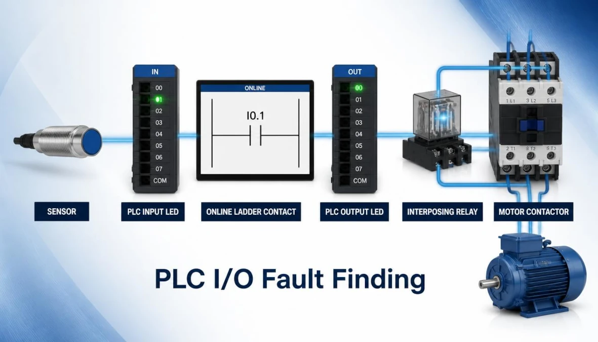
6. Trace PLC Logic Systematically
Start at the output or sequence transition that failed and work backward. Find the first contact, comparison, timer, counter, alarm, mode bit, or permissive that is false. Check whether the logic uses normally open or normally closed instructions and whether the field signal is intentionally inverted. Look for manual/automatic selection, latch conditions, step numbers, recipe values, timer presets, and fault-reset logic. Avoid changing the program merely to make the rung true. Also review these common PLC programming mistakes before treating an unexpected logic state as a hardware failure.
7. Troubleshoot PLC Outputs
Confirm that the PLC logic commands the output, then compare the online bit, output LED, terminal voltage, interposing relay, protective device, and final load. If the bit is on but the LED is off, review module diagnostics. If the LED is on but no terminal voltage is present, check the output common, module supply, fuse, and channel. If voltage reaches the load but it does not operate, isolate the circuit and test the contactor coil, solenoid, motor starter, cable, and mechanical condition. When checking a motor circuit, compare the measured value with the expected full-load current using the Motor Current Calculator.
8. Check Networks and Remote I/O
For Ethernet, Modbus, PROFIBUS, PROFINET, EtherNet/IP, or other networks, check device power, cable condition, connector seating, termination, address, baud rate, duplicate nodes, link LEDs, and diagnostic counters. A PLC may remain in RUN while remote I/O is unavailable. If the fault involves supervisory monitoring rather than controller execution, our SCADA vs PLC guide explains the different system roles. Record which nodes fail together because a common power supply, switch, trunk cable, or segment fault may be the real cause.
9. Verify Analog Signals and Scaling
Separate the raw electrical signal from the engineering value. Measure the actual 4–20 mA, 0–10 V, thermocouple, or RTD signal when safe. Compare it with the module raw count and scaled PLC value. Check channel type, range, wiring, shield grounding, open-circuit detection, conversion formula, and alarm limits. A correct raw value with an incorrect engineering value normally indicates a scaling or data-type problem.
10. Controlled Restart and Documentation
After the repair, remove forces, jumpers, temporary overrides, test code, and bypasses. Restore guards and covers. Confirm the PLC is in the required mode, acknowledge alarms, and restart at reduced risk according to the site procedure. Test the affected sequence and associated protections. Record the root cause, measurements, replaced components, program version, backup location, and preventive action.
Use this PLC troubleshooting checklist as a structured fault-finding record, and adapt every step to the machine manufacturer’s instructions and your site safety procedure.
Useful PLC Troubleshooting Tools
- Current electrical drawings and I/O list
- Manufacturer manuals and error-code references
- Correct programming cable and licensed software
- CAT-rated multimeter and suitable test leads
- Network diagnostic tools where applicable
- Approved lockout/tagout equipment
- Known-good backup and change log
For manufacturer documentation and diagnostic references, consult Siemens Industry Online Support.
When to Escalate a PLC Fault
Stop troubleshooting and escalate the fault when the work requires defeating a safety function, opening energized equipment beyond your authorization, changing a validated program, or replacing a safety-rated component. Escalation is also appropriate when the same fault returns after repair, several network nodes fail together, diagnostic data conflicts with field measurements, or no current backup and change record is available. Provide the next technician or engineer with the exact alarm, time, machine state, measurements, module address, program version, and actions already completed.
PLC Fault Record Template
A consistent fault record reduces repeat failures and prevents the next shift from repeating the same checks. Copy the fields below into the site maintenance system or job report.
| Record Field | What to Enter |
|---|---|
| Fault identity | Machine, station, PLC, module, channel and alarm code |
| Operating condition | Date, time, mode, recipe, cycle step and machine speed |
| Evidence | LED states, diagnostic message, voltage, current or network data |
| Root cause | Failed component, wiring fault, logic condition or configuration issue |
| Corrective action | Repair completed, part number, parameter or approved program change |
| Verification | Safety checks, test cycles, restored forces and final operating result |
PLC Troubleshooting FAQs
What should I check first when a PLC machine stops?
Make the machine safe, confirm the reported symptom, and check control power, PLC status LEDs, safety circuits, alarms, and diagnostics before changing the program.
Can a PLC be in RUN while the machine does not operate?
Yes. The CPU can remain in RUN while an interlock is open, remote I/O is offline, an output fuse has failed, a field device is damaged, or a mechanical condition prevents operation.
Should I force an output during troubleshooting?
Forcing can create unexpected motion or defeat the normal sequence. Use it only under an approved site procedure, risk assessment, and qualified supervision. Never force safety functions.
Why should the error code be recorded before reset?
A reset or power cycle may remove diagnostic evidence. Recording the code, time, module, and operating state makes intermittent faults easier to investigate. This PLC troubleshooting checklist helps preserve a repeatable sequence for the next investigation.
Related TechVoltLab Tools
- Current Calculator — calculate current using power, voltage or resistance.
- Load Calculator — estimate connected electrical load and operating current.
Final Thoughts
Effective PLC troubleshooting is not guesswork. The safest and fastest method is to preserve the evidence, identify the first failed condition, and follow the signal path from the field device through the PLC logic to the final output. Use this PLC troubleshooting checklist consistently, document every confirmed finding, and change only one controlled item at a time. A disciplined record turns a one-time repair into useful maintenance knowledge and helps prevent the same failure from stopping production again.
