 Tech Volt Lab Automation | PLC | SCADA | Electrical | Electronics

Related Articles

A Power Factor Calculator determines power factor, real power, apparent power, reactive power, phase angle, line current, or the reactive compensation required to improve an AC electrical system. Electricians, engineers, panel builders, maintenance technicians, automation professionals, and students can use it for single-phase and three-phase calculations. Power factor affects the current required to deliver a specified amount of real power. A low power factor can increase current, cable losses, voltage drop, and the loading of transformers, generators, switchgear, and distribution circuits. Some utility tariff structures may also include penalties or demand adjustments related to poor power factor.
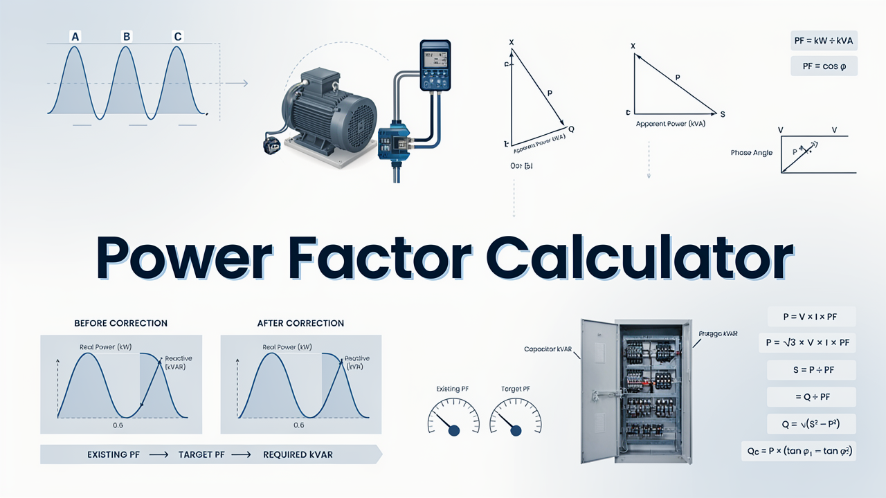
Correct calculation requires a clear distinction between kW, kVA, and kVAR. The waveform type, load condition, measurement method, voltage, phase arrangement, and possible harmonic distortion also matter. This guide explains the principal formulas, numerical examples, correction calculations, and practical limitations.
What Is a Power Factor Calculator?
A Power Factor Calculator evaluates the relationship between real power and apparent power in an AC circuit. Power factor is a dimensionless ratio normally expressed as a decimal from 0 to 1 or as a percentage. A value of 0.90 is equivalent to 90% power factor.
Depending on the selected calculation, the required inputs may include real power in kW, apparent power in kVA, reactive power in kVAR, voltage, current, phase type, frequency, initial power factor, and target power factor. The output may be power factor, phase angle, line current, or required capacitor compensation in kVAR.
The calculator is useful for preliminary distribution studies, motor-load reviews, transformer loading, capacitor-bank planning, generator assessments, and troubleshooting. The calculated result is not automatically a final capacitor or equipment rating. Harmonics, switching steps, resonance, voltage variation, load profile, and manufacturer requirements may require further analysis.
How Does a Power Factor Calculator Work?
The calculator applies the formula that matches the available electrical values. If kW and kVA are known, it divides real power by apparent power. If kW and kVAR are known, it first calculates apparent power and then determines the power factor.
- Select power factor, power, current, phase angle, or correction calculation.
- Select single-phase or three-phase AC where required.
- Enter the known kW, kVA, kVAR, voltage, or current values.
- Enter initial and target power factor for a correction calculation.
- Confirm whether the power factor is leading or lagging where relevant.
- Calculate and review the result together with its unit.
The calculator provides a mathematical result from the entered values. It does not replace power-quality measurements, capacitor-bank manufacturer data, equipment nameplates, utility requirements, applicable standards, local electrical regulations, or professional engineering judgment.
Step-by-Step Process
- Select the required calculation type.
- Choose single-phase or three-phase AC when calculating current or power.
- Enter the primary known value, such as kW, kVA, or kVAR.
- Enter the remaining required electrical values.
- Use line-to-line voltage for the balanced three-phase formulas shown below.
- Enter power factor as a decimal, such as 0.85 rather than 85.
- For correction calculations, enter a target power factor greater than the initial value but not above 1.
- Calculate and check whether the result represents PF, kW, kVA, kVAR, amperes, or degrees.
- Compare critical results with measurements, utility requirements, and equipment information.
Power Factor Calculator Formula
Power factor is the ratio of real power to apparent power. For a general AC system, the basic formula is:
PF = P ÷ S
PF = kW ÷ kVA
Real power P performs useful work and is measured in watts or kilowatts. Apparent power S represents the combined voltage-current requirement and is measured in volt-amperes or kilovolt-amperes.
Apparent Power from kW and kVAR
S = √(P² + Q²)
Reactive power Q is measured in VAR or kVAR. When real power is entered in kW and reactive power in kVAR, the resulting apparent power is in kVA.
PF = P ÷ √(P² + Q²)
Reactive Power Formula
Q = √(S² − P²)
This formula calculates reactive power when real and apparent power are known. The values must use corresponding units, such as kW and kVA, to obtain the result in kVAR.
Power Factor and Phase Angle
PF = cos φ
φ = cos−1(PF)
Q = P × tan φ
The angle φ represents the phase displacement between fundamental voltage and current for a sinusoidal system. The relationship PF = cos φ describes displacement power factor. With nonlinear loads and distorted current, true power factor can be lower than displacement power factor, so a suitable power-quality meter may be required.
Single-Phase Power Factor
P = (V × I × PF) ÷ 1,000
PF = (P × 1,000) ÷ (V × I)
I = (P × 1,000) ÷ (V × PF)
In these formulas, P is the real input power in kW, V is the RMS voltage across the single-phase load, and I is the RMS current in amperes.
Three-Phase Power Factor
P = (√3 × VLL × I × PF) ÷ 1,000
PF = (P × 1,000) ÷ (√3 × VLL × I)
I = (P × 1,000) ÷ (√3 × VLL × PF)
These formulas apply to a reasonably balanced three-phase load. Voltage VLL is the RMS line-to-line voltage. Where phase currents or voltages are unbalanced, measure and assess the phases individually instead of relying only on a balanced-load calculation.
Required Power Factor Correction
Qc = P × [tan(φ1) − tan(φ2)]
φ1 = cos−1(PF1)
φ2 = cos−1(PF2)
The result Qc is the theoretical capacitive reactive power required to change the initial power factor PF1 to the target power factor PF2. When real power is entered in kW, the correction result is in kVAR.
A calculated kVAR value is not enough to finalize a capacitor bank. Standard step sizes, load variation, voltage, frequency, harmonics, switching method, ambient temperature, discharge requirements, resonance risk, and manufacturer recommendations must also be evaluated.
Formula Explanation
| Symbol | Description |
|---|---|
| PF | True power factor expressed as a decimal or percentage |
| PF1 | Initial power factor before correction |
| PF2 | Target power factor after correction |
| P | Real electrical input power in watts or kilowatts |
| Q | Reactive power in VAR or kVAR |
| S | Apparent power in VA or kVA |
| Qc | Required capacitive compensation in VAR or kVAR |
| V | Single-phase RMS voltage in volts |
| VLL | Three-phase RMS line-to-line voltage in volts |
| I | RMS load or line current in amperes |
| φ | Voltage-current phase angle in degrees or radians |
| φ1 | Initial phase angle before correction |
| φ2 | Target phase angle after correction |
| √3 | Balanced three-phase conversion factor, approximately 1.732 |
| cos | Cosine trigonometric function |
| tan | Tangent trigonometric function |
Keep power units consistent. Use W, VAR, and VA together or use kW, kVAR, and kVA together. Enter 85% power factor as 0.85. A power factor may be described as lagging for predominantly inductive loads or leading for predominantly capacitive conditions.
Interactive Power Factor Calculator
Use the calculator below to enter the required values and obtain the calculated engineering result.
⚡ Power Factor Calculator
Calculate power factor from real, apparent, or reactive power.
Power Factor Result
Enter values and press Calculate.
PF = kW ÷ kVA
kVA = √(kW² + kVAR²)
Example 1 – Calculate Power Factor from kW and kVA
An electrical installation consumes 80 kW of real power while the measured apparent power is 100 kVA. Calculate its power factor.
Given: P = 80 kW and S = 100 kVA
Formula: PF = P ÷ S
Calculation: PF = 80 ÷ 100 = 0.80
Final result: PF = 0.80 or 80%
The installation uses 80 kW of real power while requiring 100 kVA from the source. Whether correction is technically or financially justified depends on the utility tariff, system capacity, operating hours, and load profile.
Example 2 – Calculate PF from kW and kVAR
A load consumes 60 kW of real power and 45 kVAR of reactive power. Calculate apparent power, power factor, and phase angle.
Apparent power: S = √(60² + 45²)
S = √(3,600 + 2,025) = √5,625 = 75 kVA
Power factor: PF = 60 ÷ 75 = 0.80
Phase angle: φ = cos−1(0.80) = 36.87°
The apparent power is 75 kVA, the power factor is 0.80, and the displacement angle is approximately 36.87 degrees. The angle relationship assumes a sinusoidal condition and should not be used as the only indicator of true power factor for a highly distorted load.
Example 3 – Power Factor from Real and Apparent Power
A load using 45 kW from a 50 kVA supply has a power factor of 0.90. Select the kW and kVA method and enter both values.
Example 4 – Power Factor from kW and kVAR
For a 30 kW load with 18 kVAR reactive power, select the kW and kVAR method. The calculator gives about 34.99 kVA and a power factor of 0.857.
Practical Field Considerations for Power Factor Calculations
Power factor varies with equipment loading. An induction motor may have a lower power factor at light load than near its rated operating point. A single measurement taken during reduced production may therefore not represent the facility’s normal or maximum operating condition.
During commissioning, use an instrument capable of measuring true kW, kVA, kVAR, and power factor. Calculating power factor from a simple voltage and current reading can be misleading because voltage multiplied by current provides apparent power, while real power must also be known.
Nonlinear loads such as variable frequency drives, rectifiers, UPS systems, switched-mode power supplies, and electronic lighting can produce distorted current. In these systems, true power factor includes both phase displacement and distortion. Conventional phase-angle correction alone may not solve the complete power-quality issue.
Fixed capacitors can cause leading power factor or overvoltage when the associated inductive load is disconnected. Automatic power factor correction equipment uses switched steps to follow changing reactive-power demand, but its controller settings, switching sequence, and current-transformer installation must be correct.
Capacitors and system inductance can create resonant conditions near harmonic frequencies. Where harmonic-producing loads are present, a power-quality study may be required to determine whether detuned reactors, harmonic filters, or another correction method is appropriate.
Applications of a Power Factor Calculator
Industrial Applications
- Reviewing motor, pump, fan, compressor, and production-line loads.
- Estimating capacitor-bank compensation requirements.
- Comparing kW, kVA, and kVAR demand.
- Assessing transformer and generator capacity utilization.
Electrical Distribution Applications
- Calculating current at different power-factor values.
- Reviewing feeder and switchgear loading.
- Checking utility-meter power values.
- Supporting preliminary reactive-power studies.
Automation and Maintenance Applications
- Reviewing VFD and nonlinear load measurements.
- Troubleshooting automatic capacitor-bank operation.
- Comparing calculated values with power-quality analyzer data.
- Monitoring changes after equipment or process modifications.
Educational Applications
- Understanding the power triangle.
- Studying the relationship between kW, kVA, and kVAR.
- Practising single-phase and three-phase formulas.
- Learning how correction changes reactive power and current.
Advantages of a Power Factor Calculator
- Reduces repetitive manual calculations.
- Calculates PF from different combinations of known values.
- Supports kW, kVA, kVAR, current, and phase-angle calculations.
- Estimates theoretical capacitor correction requirements.
- Helps compare system current before and after correction.
- Supports troubleshooting and preliminary distribution reviews.
- Helps students understand power-triangle relationships.
Limitations
- The result depends on correct voltage, current, and power measurements.
- Balanced three-phase formulas may not represent an unbalanced installation.
- The relationship PF = cos φ alone does not describe distortion power factor.
- Power factor can change significantly with equipment loading.
- Theoretical correction kVAR does not define a complete capacitor-bank design.
- Harmonics and resonance require additional analysis.
- Utility billing methods and correction requirements vary.
- The calculator does not replace manufacturer data, applicable standards, or professional judgment.
Common Mistakes
- Mixing W, kW, VA, kVA, VAR, and kVAR without conversion.
- Entering 85 instead of 0.85 for an 85% power factor.
- Confusing power factor with motor efficiency.
- Using phase-to-neutral voltage in the shown three-phase formula.
- Calculating PF from voltage and current without measuring real power.
- Ignoring whether reactive power is inductive or capacitive.
- Treating displacement PF as true PF for a nonlinear load.
- Selecting an exact capacitor-bank size without considering standard steps.
- Ignoring harmonics, resonance, and changing load conditions.
- Assuming power factor correction always produces proportional kWh savings.
When apparent power is not known, determine operating amperes with the Current Calculator. To estimate the financial effect of real-power use, continue with the Energy Cost Calculator.
Frequently Asked Questions
What is a Power Factor Calculator?
It calculates power factor or related values such as kW, kVA, kVAR, phase angle, current, and theoretical correction kVAR.
What is the basic power factor formula?
The basic formula is PF = kW ÷ kVA, where kW is real power, and kVA is apparent power.
What is a good power factor?
The appropriate target depends on the utility, equipment, and installation. Many projects select a target below unity to reduce the risk of overcorrection.
What causes low power factor?
Common causes include lightly loaded induction motors, transformers, welding equipment, discharge lighting, and other loads requiring reactive power.
Does low power factor increase current?
Yes. For the same real power and voltage, a lower power factor requires more current from the supply.
Does power factor correction reduce kWh consumption?
Correction can reduce current and upstream distribution losses, but it does not directly reduce the useful energy required by the load. Billing benefits depend on the tariff.
Can capacitor kVAR be selected from the calculated value alone?
No. Load variation, standard steps, harmonics, resonance, voltage, frequency, switching, and manufacturer requirements must also be checked.
Why can meter power factor differ from cos φ?
A true power-factor meter includes the effect of waveform distortion, while cos φ generally represents fundamental displacement power factor.
Related Electrical Calculators
Helpful Electrical Engineering Resources
Conclusion
A Power Factor Calculator determines the relationship among real power, apparent power, and reactive power. It can also calculate phase angle, single-phase or three-phase current, and the theoretical kVAR required for power factor correction.
These results support motor-load reviews, transformer and generator assessments, distribution planning, capacitor-bank studies, utility-demand analysis, and electrical troubleshooting. Actual power factor may change with loading, waveform distortion, voltage, and operating conditions.
Use the Power Factor Calculator from Tech Volt Lab as a practical calculation and verification aid. Before installing correction equipment, compare the results with power-quality measurements, the current utility tariff, manufacturer documentation, and a suitable engineering assessment.
Explore More Engineering Calculators
Discover more free electrical and automation calculators designed for electricians, PLC programmers, maintenance technicians, and engineers.
View All Calculators