 Tech Volt Lab Automation | PLC | SCADA | Electrical | Electronics

Related Articles
A Frequency Calculator determines frequency, period, wavelength, angular frequency, motor supply frequency, pulse rate, or RC cutoff frequency from known engineering values. Electricians, electronics technicians, automation engineers, maintenance teams, PLC programmers, and students can use it to complete common frequency-related calculations without repeatedly rearranging formulas. Frequency is important wherever a signal, waveform, machine, or repeating event operates in cycles. It affects AC power systems, motor speed, encoder signals, communication circuits, filters, oscilloscopes, timers, counters, and industrial control equipment. A wrong frequency value can lead to incorrect speed calculations, unreliable measurements, unsuitable filter settings, or improper control-system configuration.
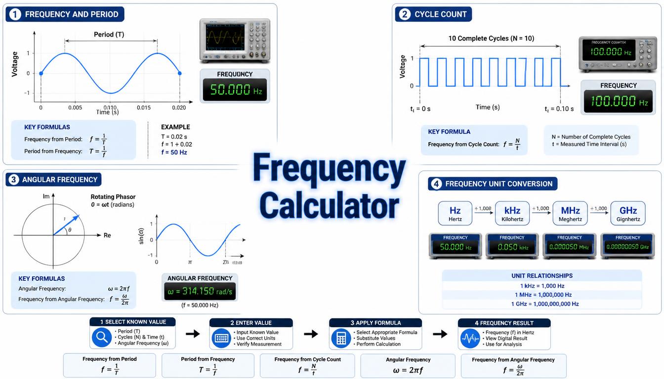
This guide explains the main frequency formulas, required units, practical examples, and field considerations. Correct input units are especially important because milliseconds, microseconds, revolutions per minute, pulses per revolution, and component values must normally be converted before they can be used in standard formulas.
What Is a Frequency Calculator?
A Frequency Calculator is an engineering tool that evaluates how often a cycle or event occurs within a specified time. The basic result is normally expressed in hertz, where one hertz represents one complete cycle per second. Depending on the selected calculation type, the tool may also calculate period, wavelength, angular frequency, synchronous motor speed, pulse frequency, or an RC circuit’s cutoff frequency.
Typical inputs include time per cycle, number of cycles, elapsed time, wave velocity, wavelength, motor pole count, rotational speed, encoder pulses per revolution, resistance, and capacitance. The required inputs change with the selected formula. For example, calculating frequency from period needs only the period, while calculating an encoder pulse frequency requires both RPM and pulses per revolution.
The result is useful for preliminary design, commissioning, troubleshooting, education, and verification. It should not automatically be treated as a final equipment setting or component rating. Manufacturer documentation, equipment nameplates, measurement tolerances, applicable standards, and actual operating conditions remain important references.
How Does a Frequency Calculator Work?
The calculator applies the formula associated with the calculation mode selected by the user. It first converts the entered values into compatible base units, performs the calculation, and then displays the result in the requested unit, such as Hz, kHz, MHz, seconds, milliseconds, radians per second, or revolutions per minute.
- Select the required calculation, such as period to frequency or RPM to pulse frequency.
- Enter the known numerical values.
- Select the correct units for time, resistance, capacitance, speed, or wavelength.
- Enter any additional factor, such as motor poles or encoder pulses per revolution.
- Calculate the result and check its displayed unit.
- Compare critical results with equipment data and actual measurements.
The calculation does not replace manufacturer instructions, nameplate ratings, electrical standards, local codes, or professional engineering judgment. It provides a mathematical result based on the information entered by the user.
Step-by-Step Process
- Select the frequency calculation type that matches the available information.
- Enter the primary value, such as period, RPM, wavelength, or resistance.
- Select its unit, paying particular attention to milli, micro, kilo, and mega prefixes.
- Enter the remaining required values, such as pole count, wave velocity, capacitance, or pulses per revolution.
- Confirm that all conversion factors and input units are correct.
- Click the Calculate button.
- Review the result together with its unit.
- Compare the result with equipment nameplate data, design documents, or a suitable measuring instrument.
- Apply the necessary operating limits, tolerances, and safety requirements before using the result.
Frequency Calculator Formula
The standard relationship between frequency and period is:
f = 1 ÷ T
Here, f is frequency in hertz, and T is the duration of one complete cycle in seconds. If the period is entered in milliseconds or microseconds, convert it to seconds first.
Period from Frequency
T = 1 ÷ f
This rearranged formula calculates the time taken by one cycle. The result is in seconds when frequency is entered in hertz. Multiply seconds by 1,000 for milliseconds or by 1,000,000 for microseconds.
Frequency from several Cycles
f = N ÷ Δt
In this formula, N is the number of complete cycles observed during elapsed time Δt. The time interval must be expressed in seconds to obtain frequency in hertz. Counters and data-acquisition systems commonly use this method.
Wavelength and Frequency
f = v ÷ λ
λ = v ÷ f
The symbol v represents wave velocity in metres per second, while λ represents wavelength in metres. The correct propagation velocity must be used for the actual medium. Electromagnetic waves in cables, for example, may travel more slowly than they do in free space.
Angular Frequency
ω = 2 × π × f
f = ω ÷ (2 × π)
Angular frequency describes the rate of phase change and is measured in radians per second. It is widely used in AC circuit analysis, control theory, signal processing, and mechanical vibration calculations. The constant π is approximately 3.14159.
AC Motor Frequency and Synchronous Speed
Ns = (120 × f) ÷ p
f = (Ns × p) ÷ 120
The synchronous speed Ns is expressed in revolutions per minute, f is the electrical supply frequency in hertz, and p is the total number of motor poles. A practical induction motor normally runs below synchronous speed because torque production requires slip. Therefore, the formula does not directly predict the loaded shaft speed of an induction motor.
Encoder and Pulse Frequency
fp = (RPM × PPR) ÷ 60
RPM = (60 × fp) ÷ PPR
Pulse frequency fp is measured in pulses per second, which is numerically equivalent to hertz. PPR is the number of pulses produced during one revolution. For quadrature encoders, confirm whether the control system uses the encoder’s stated pulse count or counts one, two, or four edges per cycle.
RC Cutoff Frequency
fc = 1 ÷ (2 × π × R × C)
This formula calculates the ideal cutoff frequency of a first-order RC filter. Resistance R must be entered in ohms and capacitance C in farads. At the cutoff frequency, the output magnitude of an ideal first-order filter is approximately 0.707 of its passband value, corresponding to about −3 dB.
Formula Explanation
| Symbol | Description |
|---|---|
| f | Frequency in hertz (Hz), where 1 Hz equals 1 cycle per second |
| T | Period of one cycle in seconds (s) |
| N | Number of complete cycles or events counted |
| Δt | Elapsed measurement time in seconds (s) |
| v | Wave propagation velocity in metres per second (m/s) |
| λ | Wavelength in metres (m) |
| ω | Angular frequency in radians per second (rad/s) |
| π | Mathematical constant, approximately 3.14159 |
| Ns | Synchronous motor speed in revolutions per minute (RPM) |
| p | Total number of motor poles |
| fp | Pulse frequency in pulses per second or hertz |
| PPR | Pulses generated per revolution |
| RPM | Rotational speed in revolutions per minute |
| fc | RC filter cutoff frequency in hertz (Hz) |
| R | Resistance in ohms (Ω) |
| C | Capacitance in farads (F) |
Common conversions include 1 kHz = 1,000 Hz, 1 MHz = 1,000,000 Hz, 1 ms = 0.001 s, 1 µs = 0.000001 s, 1 kΩ = 1,000 Ω, and 1 µF = 0.000001 F. Using base units before substitution helps prevent errors caused by engineering prefixes.
Interactive Frequency Calculator
Use the calculator below to enter the required values and obtain the calculated engineering result.
⚡ Frequency Calculator
Calculate frequency from period, rotational speed and poles, or wavelength and propagation speed.
Frequency Result
Enter values and press Calculate.
f = 1 ÷ T
f = RPM × poles ÷ 120
f = v ÷ λ
Example 1 – Calculate Frequency from Period
A repeating AC waveform has a measured period of 20 milliseconds. Calculate its frequency.
Given: T = 20 ms
Convert the period: 20 ms = 20 ÷ 1,000 = 0.020 s
Formula: f = 1 ÷ T
Calculation: f = 1 ÷ 0.020 = 50 Hz
The waveform completes 50 cycles every second. When checking a live electrical system, technicians should use appropriately rated measuring equipment and follow the required electrical safety procedures.
Example 2 – Calculate Motor Supply Frequency
Determine the electrical frequency required to produce a synchronous speed of 1,500 RPM in a four-pole AC motor.
Given: Ns = 1,500 RPM and p = 4 poles
Formula: f = (Ns × p) ÷ 120
Calculation: f = (1,500 × 4) ÷ 120 = 50 Hz
The calculated synchronous frequency is 50 Hz. A loaded induction motor will usually operate below 1,500 RPM because of slip. When setting a variable frequency drive, also check the motor nameplate, rated voltage-to-frequency relationship, cooling requirements, permissible speed range, and drive manufacturer instructions.
Example 3 – Frequency from Motor RPM and Poles
A four-pole motor running at 1,500 RPM corresponds to a 50 Hz supply. Select the RPM and poles mode, enter 1500 RPM and 4 poles, and the calculator returns 50 Hz.
Example 4 – Frequency from Wave Speed and Wavelength
For a sound wave travelling at 343 m/s with a wavelength of 0.686 m, select the wave-speed mode. The calculator returns a frequency of 500 Hz.
Practical Field Considerations for Frequency Calculations
In practical installations, the calculated value should be compared with an actual measurement whenever the signal or equipment condition permits. Digital multimeters, oscilloscopes, frequency counters, tachometers, and PLC diagnostic functions can measure frequency, but each instrument has bandwidth, resolution, input-level, and signal-shape limitations.
Noise, contact bounce, harmonics, weak sensor signals, poor grounding, and incorrect trigger thresholds can create unstable readings or extra pulse counts. Shielding, cable routing, filtering, input configuration, and a suitable measurement time window may be necessary for reliable industrial signals.
A VFD output contains a pulse-width-modulated waveform. The fundamental motor frequency and the drive’s carrier or switching frequency are different quantities. Use VFD-compatible test equipment and follow the drive manufacturer’s measurement procedure instead of assuming that every meter will interpret the output correctly.
For sampled signals, the sampling rate must be high enough to represent the frequency of interest. Inadequate sampling can cause aliasing, where a higher-frequency signal appears as a false lower frequency. Appropriate sampling, input filtering, and signal conditioning should therefore be considered in PLC, data-logging, and digital measurement applications.
Applications of a Frequency Calculator
Electrical and Electronics Applications
- Converting AC waveform period into frequency.
- Calculating RC filter cutoff frequency.
- Finding angular frequency for impedance and phase calculations.
- Relating wavelength to propagation speed and frequency.
Motor and Drive Applications
- Estimating synchronous motor speed from supply frequency.
- Calculating the frequency associated with a target synchronous speed.
- Checking preliminary VFD speed and frequency relationships.
Automation Applications
- Calculating encoder pulse rates for PLC high-speed counters.
- Converting proximity-sensor pulses into machine speed.
- Checking flowmeter, turbine, and production counter signals.
- Configuring timer, counter, and data-acquisition parameters.
Maintenance and Educational Applications
- Comparing expected frequency with instrument readings during troubleshooting.
- Checking machine-speed calculations against tachometer data.
- Studying the relationships among frequency, period, speed, and wavelength.
Advantages of a Frequency Calculator
- Reduces repetitive rearrangement of frequency formulas.
- Supports consistent conversion between time and frequency units.
- Helps compare motor, encoder, filter, and waveform calculations.
- Assists with preliminary PLC input and measurement-range checks.
- Makes formula relationships easier for students to understand.
- Provides a convenient result for comparison with measured or rated values.
Limitations
- The result depends on the accuracy of every entered value and unit.
- Noise and waveform distortion can make measured frequency unstable.
- The synchronous-speed formula does not include induction-motor slip.
- The basic encoder formula does not automatically account for quadrature edge multiplication.
- The RC formula represents an ideal first-order circuit and does not include every parasitic effect.
- Calculated results do not confirm that an instrument, PLC input, motor, or drive is suitably rated.
- Manufacturer documentation and applicable engineering requirements remain the primary final references.
- The calculator does not replace professional judgment or safe measurement procedures.
Common Mistakes
- Entering milliseconds as seconds without applying the required conversion.
- Mixing hertz, kilohertz, and megahertz.
- Using kilohms or microfarads directly in a formula that requires ohms and farads.
- Confusing pulse frequency with mechanical revolutions per second.
- Using the wrong encoder PPR value or ignoring the controller’s edge-counting mode.
- Treating synchronous motor speed as the actual loaded shaft speed.
- Confusing a VFD’s fundamental output frequency with its carrier frequency.
- Using the speed of light in free space for every transmission medium.
- Ignoring instrument bandwidth, sampling rate, or signal amplitude.
- Applying a calculated result without checking manufacturer limits and operating conditions.
For motor applications, compare frequency and pole count with the RPM Calculator. For AC equipment supplied through a transformer, review voltage relationships with the Transformer Calculator.
Frequently Asked Questions
What is a Frequency Calculator?
It is a tool that calculates frequency or related values such as period, wavelength, angular frequency, motor speed, pulse rate, and RC cutoff frequency.
What is the basic frequency formula?
The basic formula is f = 1 ÷ T, where f is frequency in hertz, and T is the period of one cycle in seconds.
What does one hertz mean?
One hertz means that one complete cycle or repeating event occurs every second.
How do I convert milliseconds to hertz?
First, divide the period in milliseconds by 1,000 to obtain seconds. Then calculate frequency using f = 1 ÷ T.
Can frequency be calculated from motor RPM?
Yes. For synchronous speed, use f = (Ns × p) ÷ 120. Actual induction-motor shaft speed is normally lower because of slip.
How is encoder frequency calculated?
Multiply shaft RPM by pulses per revolution and divide by 60. Confirm how the connected controller counts quadrature edges.
Why can measured frequency differ from the calculated result?
Differences may result from input tolerance, motor slip, signal noise, waveform distortion, measurement resolution, sampling rate, or changing operating conditions.
Can the calculated value be used as a final equipment setting?
Use it as a calculation and verification aid. Check critical settings against manufacturer documentation, nameplate data, applicable requirements, and actual operating conditions.
Related Electrical Calculators
- Period Calculator
- Wavelength Calculator
- RPM Calculator
- RPM to Hz Calculator
- RC Time Constant Calculator
- Inductive Reactance Calculator
Helpful Electrical Engineering Resources
Conclusion
A Frequency Calculator provides a practical way to calculate hertz, period, wavelength, angular frequency, synchronous motor speed, encoder pulse rate, and RC cutoff frequency. It brings several related formulas together while helping users maintain consistent units.
These calculations support waveform analysis, motor and VFD work, PLC high-speed input selection, encoder applications, filter design, maintenance, and technical education. Their usefulness still depends on correct inputs, a suitable formula, and a clear understanding of the difference between ideal calculations and actual operating values.
Use the Frequency Calculator from Tech Volt Lab as a calculation and verification aid, then compare critical results with measurements, manufacturer documentation, equipment nameplates, and applicable engineering requirements before making final decisions.
Explore More Engineering Calculators
Discover more free electrical and automation calculators designed for electricians, PLC programmers, maintenance technicians, and engineers.
View All Calculators