 Tech Volt Lab Automation | PLC | SCADA | Electrical | Electronics

Related Articles
A Reactance Calculator determines the opposition that an inductor or capacitor presents to alternating current at a specified frequency. Electricians, electronics engineers, maintenance technicians, automation professionals, panel designers, and students can use it to calculate inductive reactance, capacitive reactance, net RLC reactance, and related phase behavior.
Reactance affects AC, voltage distribution, phase angle, power factor, resonance, filter response, and component loading. Unlike resistance, reactance changes with frequency, so a correct calculation must use the actual operating or test frequency and consistent inductance or capacitance units.
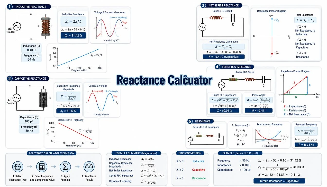
This guide explains inductive and capacitive formulas, series and parallel RLC behavior, resonance, unit conversions, numerical examples, and practical measurement limitations. It also shows why calculated ideal reactance may differ from a real coil or capacitor under working conditions.
What Is a Reactance Calculator?
A Reactance Calculator finds frequency-dependent opposition in an AC circuit. Its principal inputs are frequency in hertz and either inductance in henries or capacitance in farads. Some calculation modes may also accept resistance, both L and C values, or a target reactance to solve for an unknown component value or frequency.
The result is expressed in ohms. Inductive reactance is assigned a positive imaginary sign, while capacitive reactance is assigned a negative imaginary sign in complex impedance. Calculators often display XL and XC as positive magnitudes, then apply the correct signs when calculating net reactance.
Reactance calculations are used for coils, capacitors, filters, transformers, motors, solenoids, audio circuits, sensor interfaces, and resonant networks. The output is a theoretical result from the entered model, not automatically a measured value or final component rating. Tolerance, loss, saturation, temperature, parasitic elements, and waveform conditions can affect real behavior.
How Does a Reactance Calculator Work?
The calculator converts the entered values to hertz, henries, and farads. It then applies the selected inductive, capacitive, net series RLC, resonance, or reverse calculation. Because XL and XC respond oppositely to frequency, the calculation type and frequency must match the physical circuit.
- Select inductive, capacitive, net RLC, or reverse calculation.
- Enter the known frequency and component value.
- Select the correct Hz, kHz, H, mH, µH, F, µF, or nF unit.
- Enter both L and C values when calculating net reactance or resonance.
- Calculate and identify whether the result is inductive, capacitive, or resonant.
Compare the result with component tolerances, manufacturer frequency curves, nameplate information, measurements, applicable standards, and local electrical requirements. A calculator does not replace suitable test equipment or professional engineering judgment.
Step-by-Step Process
- Select inductive reactance, capacitive reactance, series RLC, parallel LC, resonance, or an unknown-value calculation.
- Enter the AC operating or test frequency.
- Select the frequency unit and confirm any kHz or MHz conversion.
- Enter inductance, capacitance, or both as required.
- Select the correct component unit, such as mH, µH, µF, or nF.
- Check conversions before calculating.
- Review XL, XC, or net reactance in ohms.
- Confirm whether the circuit is net inductive or capacitive at that frequency.
- Compare important results with measurements and manufacturer information.
Reactance Calculator Formula
Reactance is the imaginary component of impedance and is measured in ohms. Under the standard passive sign convention, an ideal inductor has positive reactance and an ideal capacitor has negative reactance:
Z = R + jX
ZL = jXL
ZC = −jXC
The symbol j is the imaginary operator. XL and XC are commonly stated as positive magnitudes, while the plus or minus sign identifies the component’s effect in complex impedance.
Inductive Reactance Formula
XL = 2πfL
Inductive reactance increases directly with frequency and inductance. Use frequency in hertz and inductance in henries to obtain XL in ohms. Convert millihenries by dividing by 1,000 and microhenries by dividing by 1,000,000.
L = XL ÷ (2πf)
f = XL ÷ (2πL)
Capacitive Reactance Formula
XC = 1 ÷ (2πfC)
Capacitive reactance decreases when frequency or capacitance increases. Use frequency in hertz and capacitance in farads to obtain XC in ohms. Convert microfarads by dividing by 1,000,000 and nanofarads by dividing by 1,000,000,000.
C = 1 ÷ (2πfXC)
f = 1 ÷ (2πCX
C)Series RLC Net Reactance
X = XL − XC
Z = R + j(XL − XC)
|Z| = √[R² + (XL − XC)²]
θ = tan−1[(XL − XC) ÷ R]
A positive net result is inductive, and a negative result is capacitive. At ideal series resonance, XL equals XC, net reactance is zero, and the impedance reduces to the modeled series resistance.
Parallel LC Reactance
Parallel reactances must be combined through admittance or the reciprocal rule; they are not subtracted like series reactances.
B = 1 ÷ XC − 1 ÷ XL
Xeq = −1 ÷ B = (XL × XC) ÷ (XC − XL)
Here, B is net susceptance in siemens and Xeq is the equivalent ideal parallel reactance in ohms. At ideal parallel resonance, net susceptance is zero, and equivalent impedance tends toward infinity. Real component losses keep the measured impedance finite.
Resonant Frequency
f0 = 1 ÷ (2π√LC)
This ideal formula gives the frequency at which inductive and capacitive reactance magnitudes are equal. Use L in henries and C in farads to obtain f0 in hertz. Circuit resistance, source impedance, losses, and parasitic elements influence real resonant behavior.
Formula Explanation
| Symbol | Description |
|---|---|
| X | Net series reactance in ohms (Ω) |
| XL | Inductive reactance magnitude in ohms (Ω) |
| XC | Capacitive reactance magnitude in ohms (Ω) |
| Xeq | Equivalent ideal parallel reactance in ohms (Ω) |
| Z | Complex impedance in ohms (Ω) |
| ZL | Ideal inductor impedance in ohms (Ω) |
| ZC | Ideal capacitor impedance in ohms (Ω) |
| |Z| | Impedance magnitude in ohms (Ω) |
| R | Resistance in ohms (Ω) |
| j | Imaginary operator, where j² = −1 |
| θ | Impedance phase angle in degrees or radians |
| f | Operating frequency in hertz (Hz) |
| f0 | Ideal resonant frequency in hertz (Hz) |
| L | Inductance in henries (H) |
| C | Capacitance in farads (F) |
| B | Net susceptance in siemens (S) |
| π | Mathematical constant, approximately 3.14159 |
Interactive Reactance Calculator
Use the calculator below to enter the required values and obtain the calculated engineering result.
Calculate inductive or capacitive reactance at a selected frequency. Enter values and press Calculate.⚡ Reactance Calculator
Reactance Result
XL = 2πfL
XC = 1 ÷ (2πfC)
Example 1 – Calculate Inductive Reactance
An ideal coil has an inductance of 150 mH and operates at 50 Hz. Convert 150 mH to 0.150 H.
Formula: XL = 2πfL
XL = 2 × 3.14159 × 50 × 0.150 = 47.12 Ω
The ideal inductive reactance is 47.12 Ω at 50 Hz. The coil’s winding resistance, core loss, applied voltage, air gap, and saturation behavior must be considered separately when predicting actual current.
Example 2 – Calculate Capacitive Reactance
A 22 µF capacitor is connected to a 60 Hz AC source. Convert 22 µF to 22 × 10−6 F.
Formula: XC = 1 ÷ (2πfC)
XC = 1 ÷ (2 × 3.14159 × 60 × 22 × 10−6) = 120.57 Ω
The capacitive reactance magnitude is 120.57 Ω. This does not determine a suitable capacitor by itself; voltage rating, tolerance, ESR, ripple-current rating, dielectric type, frequency, and manufacturer information remain necessary.
Example 3 – Calculate Net Series RLC Reactance
A series circuit contains R = 20 Ω, L = 80 mH, C = 100 µF, and f = 50 Hz. Convert the reactive component values to 0.080 H and 100 × 10−6 F.
XL = 2π × 50 × 0.080 = 25.13 Ω
XC = 1 ÷ (2π × 50 × 100 × 10−6) = 31.83 Ω
X = 25.13 − 31.83 = −6.70 Ω
Z = 20 − j6.70 Ω; |Z| = 21.09 Ω; θ = −18.52°
The negative net reactance shows that the series circuit is capacitive at 50 Hz. Changing the frequency changes XL and XC in opposite directions, so this result applies only to the stated frequency.
Example 4 – Calculate Resonant Frequency
An ideal RLC circuit uses L = 50 mH and C = 100 µF. Convert these values to 0.050 H and 100 × 10−6 F.
f0 = 1 ÷ [2π√(0.050 × 100 × 10−6)]
f0 = 71.18 Hz
At approximately 71.18 Hz, ideal XL and XC are equal. Series net reactance becomes zero, while an ideal parallel LC network has zero net susceptance. Component tolerance, resistance, losses, and parasitic effects shift and soften the measured resonant response.
Practical Field Considerations for Reactance Calculations
A multimeter resistance reading does not show AC reactance. Resistance is measured under a DC test condition, whereas reactance depends on frequency and energy storage in electric or magnetic fields. Use an LCR meter or impedance analyzer when you must assess actual component behavior.
During measurement, select a test frequency and signal level appropriate for the component and application. Test leads and fixtures introduce resistance, inductance, and capacitance. Open, short, or load compensation and suitable connection techniques may be needed for demanding measurements.
Real inductors include winding resistance, core loss, inter-winding capacitance, and possible saturation. Real capacitors include ESR, leakage, dielectric loss, and lead inductance. Near self-resonance, the component can stop behaving like the simple ideal element assumed by the basic equation.
For motors, transformers, contactor coils, and solenoids, current cannot always be predicted from ideal reactance alone. Supply voltage, winding resistance, magnetic state, mechanical load, air gap, inrush, waveform distortion, temperature, and equipment construction can materially change the operating result.
Reactance formulas assume sinusoidal steady-state operation at one frequency. A distorted waveform contains harmonics, and each harmonic encounters a different reactance. VFD outputs, rectifier loads, switching power supplies, and pulse-driven coils may therefore require harmonic or time-domain analysis instead of one calculation at the fundamental frequency.
When reactance is used to estimate current, include resistance and calculate total impedance first. Dividing voltage only by XL or XC is appropriate for an ideal single reactive element, but it can be misleading for a real coil, capacitor, cable, or RLC network. Confirm that RMS voltage and the calculated impedance apply to the same frequency and operating state.
A useful field check is to calculate the expected frequency trend before taking measurements. Inductive reactance should rise as frequency increases, while capacitive reactance should fall. A substantially different trend can indicate that resistance, parasitic capacitance, lead inductance, core effects, or self-resonance has become significant in the measured range.
Applications of a Reactance Calculator
Electrical Applications
- Estimating the reactive opposition of coils and capacitors.
- Reviewing transformer, motor, and cable equivalent circuits.
- Studying current and phase behavior in AC loads.
Electronics Applications
- Designing passive filters and resonant networks.
- Comparing capacitor and inductor behavior across frequency.
- Assessing coupling, bypass, tuning, and audio circuits.
Automation and Maintenance Applications
- Reviewing relay, contactor, valve, and solenoid coils.
- Comparing calculated and measured sensor-circuit loading.
- Supporting checks on filters, capacitors, and inductive components.
Educational Applications
- Learning the difference between resistance, reactance, and impedance.
- Studying phase angle and complex AC quantities.
- Exploring series and parallel resonance.
Advantages of a Reactance Calculator
- Reduces repetitive frequency-based calculations.
- Supports consistent inductance and capacitance conversions.
- Distinguishes inductive and capacitive behavior.
- Helps compare circuit response at different frequencies.
- Supports preliminary filter and resonance analysis.
- Helps students apply AC formulas and sign conventions.
Limitations
- Results depend on correct frequency, component values, units, and circuit topology.
- Ideal equations omit resistance, ESR, leakage, core loss, and parasitic elements.
- Component values can change with temperature, voltage, current, and frequency.
- Steady-state reactance does not automatically represent inrush or switching transients.
- Parallel and series networks require different combination methods.
- Manufacturer data and suitable measurements remain necessary for final decisions.
- The calculator does not replace applicable standards or professional judgment.
Common Mistakes
- Confusing reactance with resistance or total impedance.
- Leaving frequency out of the calculation.
- Entering millihenries as henries or microfarads as farads.
- Giving capacitive reactance a positive imaginary sign in impedance.
- Subtracting reactances in a parallel network as if it were series.
- Ignoring winding resistance, ESR, and component tolerance.
- Applying a low-frequency ideal model near self-resonance.
- Using steady-state reactance as the sole basis for protection selection.
- Assuming the calculated reactance is a fixed manufacturer rating.
Use the Frequency Calculator to verify frequency-dependent values and the Capacitor Calculator for capacitance and stored-energy checks.
Frequently Asked Questions
What is a Reactance Calculator?
It calculates inductive, capacitive, or net AC reactance from frequency and component values, with the result normally expressed in ohms.
What is the inductive reactance formula?
The formula is XL = 2πfL, where frequency is in hertz and inductance is in henries.
What is the capacitive reactance formula?
The formula is XC = 1/(2πfC), where frequency is in hertz and capacitance is in farads.
How does frequency affect reactance?
Inductive reactance increases with frequency, while capacitive reactance decreases as frequency increases.
What is the difference between reactance and impedance?
Reactance is the imaginary component of AC opposition. Impedance combines resistance and reactance as a complex quantity.
What does negative net reactance mean?
A negative net series reactance means the circuit is capacitive at the selected frequency.
What happens at resonance?
At ideal resonance, XL and XC have equal magnitudes. Series net reactance becomes zero, while ideal parallel net susceptance becomes zero.
Why can measured reactance differ from the calculation?
Tolerance, temperature, signal level, ESR, winding resistance, core loss, parasitic elements, fixtures, and instrument settings affect measured results.
Related Tech Volt Lab Resources
Helpful Electrical Engineering Resources
Final Thoughts
A Reactance Calculator determines inductive, capacitive, or net RLC reactance at a selected AC frequency. It can also support reverse component calculations, phase analysis, and estimating ideal resonant frequency.
These results help with coils, capacitors, filters, resonant circuits, transformers, control components, and electronics troubleshooting. Correct topology, frequency, units, and component models are necessary because reactance changes with operating conditions.
Use the Reactance Calculator from Tech Volt Lab as a practical calculation and verification aid. Compare critical results with suitable measurements, component tolerances, manufacturer information, applicable requirements, and engineering review before final circuit or equipment decisions.
Explore More Engineering Calculators
Discover more free electrical and automation calculators designed for electricians, PLC programmers, maintenance technicians, and engineers.
View All Calculators