 Tech Volt Lab Automation | PLC | SCADA | Electrical | Electronics

Related Articles

An RPM Calculator helps engineers, electricians, maintenance technicians, machine designers, PLC programmers, and students calculate the rotational speed of motors, shafts, pulleys, gears, rollers, and other rotating components. RPM means revolutions per minute and describes how many complete rotations an object makes in one minute. Rotational speed affects machine output, conveyor movement, fan airflow, pump performance, cutting speed, bearing operation, and production timing. An incorrect RPM value can reduce process performance, damage mechanical components, create excessive vibration, or cause a machine to operate outside its designed range.
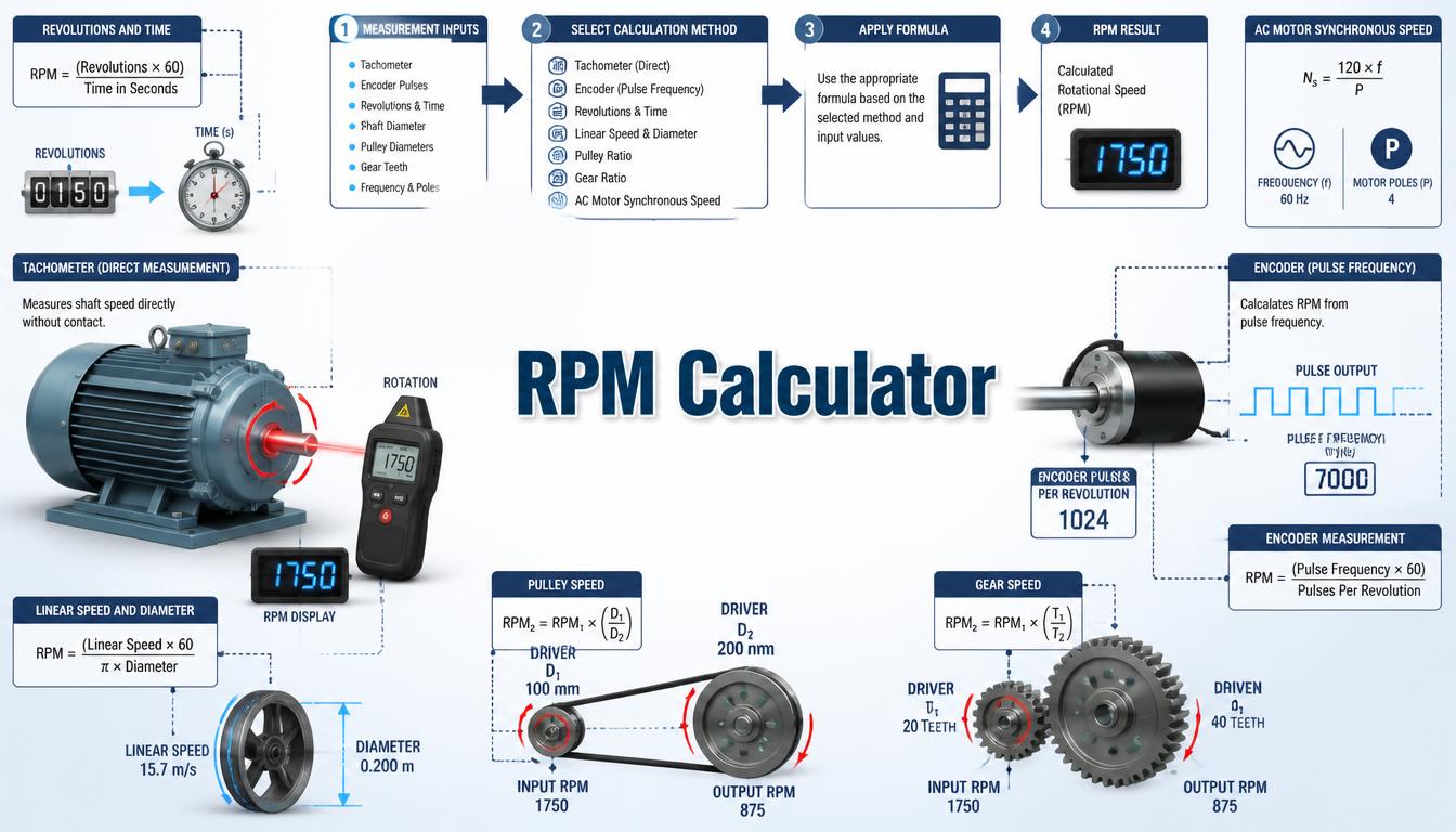
This guide explains several practical ways to calculate RPM from time, frequency, motor poles, encoder pulses, pulley diameter, gear teeth, and roller surface speed. It also covers induction-motor slip, real calculation examples, measurement methods, and common mistakes found in industrial applications.
What Is an RPM Calculator?
An RPM Calculator is a mechanical and electrical calculation tool used to determine how fast a rotating part completes full revolutions. Depending on the available information, it can calculate RPM from counted revolutions, electrical frequency, encoder pulses, gear ratio, pulley ratio, or linear surface speed.
In motor applications, the calculator can determine synchronous speed from supply frequency and the number of motor poles. For an induction motor, the actual shaft speed is slightly lower than synchronous speed when the motor produces torque. This difference is known as slip.
The tool is also useful for machines in which the motor is connected to the load through belts, pulleys, gearboxes, chains, or rollers. By entering the driving speed and transmission dimensions, technicians can estimate the final output RPM before measuring it with a tachometer or encoder.
How Does an RPM Calculator Work?
The calculator first identifies which type of speed calculation is required. Each method uses a different relationship, but every result represents complete revolutions per minute. Correct units and a clear understanding of the driving and driven components are necessary.
-
- Select the required RPM calculation method.
-
- Enter counted revolutions and elapsed time.
-
- Enter motor frequency and number of poles.
-
- Enter encoder pulse frequency and pulses per revolution.
-
- Enter driving and driven pulley diameters.
-
- Enter the numbers of teeth on the driving and driven gears.
-
- Enter roller diameter and linear speed when required.
-
- Calculate and compare the result with actual machine data.
Calculated RPM represents an ideal or expected speed unless mechanical losses, motor slip, belt slip, gearbox efficiency, load changes, and control-system behaviour are included. For maintenance or commissioning work, compare the result with a tachometer, encoder, stroboscope, VFD display, or machine-monitoring system.
Step-by-Step Process
-
- Identify the shaft, motor, roller, gear, or pulley whose speed is required.
- Select the correct calculation method for the available information.
- Confirm whether time is entered in seconds or minutes.
- Confirm whether an encoder specification uses pulses, cycles, edges, or counts per revolution.
- For motors, enter supply frequency and the actual number of poles.
- For pulleys, identify the driving and driven diameters correctly.
- For gears, identify the driver and driven tooth counts.
- For rollers, convert diameter and line-speed units before calculating.
- Calculate the expected RPM.
- Compare the calculated speed with the nameplate or measured value.
- Investigate slip, loading, transmission losses, or measurement configuration if the difference is excessive.
RPM Calculator Formula
RPM from Revolutions and Time
RPM = N ÷ tmin
RPM = (N × 60) ÷ tsec
When complete revolutions are counted over a measured time, divide the number of revolutions by time in minutes. If time is measured in seconds, multiply the revolution count by 60 before dividing by the number of seconds.
AC Motor Synchronous Speed
Ns = (120 × f) ÷ p
Synchronous speed is determined by electrical frequency and the number of motor poles. A 4-pole motor has a synchronous speed of 1,500 RPM at 50 Hz and 1,800 RPM at 60 Hz.
Induction Motor Slip
Slip (%) = [(Ns − Nr) ÷ Ns] × 100
Nr = Ns × (1 − s)
An induction motor must normally run below synchronous speed to produce torque. In the second formula, slip must be expressed as a decimal. For example, 3% slip is entered as 0.03.
RPM from Encoder Pulses
RPM = (60 × fp) ÷ PPR
Pulse frequency in pulses per second is multiplied by 60 and divided by the number of pulses per revolution. Encoder configuration must be checked carefully because PPR, CPR, quadrature edges, and PLC high-speed counter settings may describe different count values.
Pulley Speed Formula
N2 = N1 × (D1 ÷ D2).
In an ideal belt drive, speed is inversely proportional to pulley diameter. A smaller driving pulley connected to a larger driven pulley reduces output speed. Actual output may be slightly lower because of belt slip and load conditions.
Gear Speed Formula
Nout = Nin × (Tdriver ÷ Tdriven)
For a simple pair of external gears, output speed equals input speed multiplied by the driver-to-driven tooth ratio. The driven gear rotates in the opposite direction, although the RPM calculation normally reports speed magnitude.
Roller RPM from Linear Speed
RPM = (60 × v) ÷ (π × D)
When linear speed is entered in metres per second and roller diameter in metres, the result is revolutions per minute. The effective rolling diameter should be used, including any coating, belt, product thickness, or build-up that changes the circumference.
Linear Surface Speed from RPM
v = (π × D × RPM) ÷ 60
This formula converts roller or wheel RPM into theoretical surface speed. Slip between the rotating surface and the product can cause actual line speed to differ.
RPM and Angular Velocity
ω = (2 × π × RPM) ÷ 60
RPM = (60 × ω) ÷ (2 × π)
Angular velocity is expressed in radians per second. These formulas convert between RPM and angular velocity for mechanical and motion-control calculations.
Formula Explanation
| Symbol | Description |
|---|---|
| RPM | Rotational speed in revolutions per minute |
| N | Number of complete revolutions counted |
| tmin | Measurement time in minutes |
| tsec | Measurement time in seconds |
| Ns | Synchronous motor speed in RPM |
| Nr | Actual rotor speed in RPM |
| f | Electrical supply frequency in hertz |
| p | Total number of motor poles |
| s | Motor slip expressed as a decimal |
| fp | Encoder pulse frequency in pulses per second |
| PPR | Pulses generated for one shaft revolution |
| N1 | Driving pulley speed in RPM |
| N2 | Driven pulley speed in RPM |
| D1 | Driving pulley diameter |
| D2 | Driven pulley diameter |
| Tdriver | Number of teeth on the driving gear |
| Tdriven | Number of teeth on the driven gear |
| v | Linear surface speed in metres per second |
| D | Effective roller or wheel diameter in metres |
| ω | Angular velocity in radians per second |
Common AC Motor Synchronous Speeds
| Motor Poles | Speed at 50 Hz | Speed at 60 Hz |
|---|---|---|
| 2 poles | 3,000 RPM | 3,600 RPM |
| 4 poles | 1,500 RPM | 1,800 RPM |
| 6 poles | 1,000 RPM | 1,200 RPM |
| 8 poles | 750 RPM | 900 RPM |
| 10 poles | 600 RPM | 720 RPM |
| 12 poles | 500 RPM | 600 RPM |
These are synchronous speeds. The rated full-load speed of a standard induction motor is normally lower because of slip. Always use the motor nameplate or measured shaft speed when an application requires actual operating RPM.
Interactive RPM Calculator
Use the calculator below to calculate rotational speed from motor frequency, encoder pulses, pulley ratio, gear ratio, counted revolutions, or roller surface speed.
⚡ RPM Calculator
Calculate rotational speed from frequency and poles, revolutions and time, or linear speed and diameter.
RPM Result
Enter values and press Calculate.
Synchronous RPM = 120 × f ÷ poles
RPM = revolutions × 60 ÷ seconds
RPM = linear speed × 60 ÷ (π × diameter)
Example 1 – Synchronous Speed and Motor Slip
Given:
-
- Supply frequency = 50 Hz
-
- Motor poles = 4
-
- Measured rotor speed = 1,455 RPM
Ns = (120 × 50) ÷ 4 = 1,500 RPM
Slip = [(1,500 − 1,455) ÷ 1,500] × 100
Slip = 3%
The motor’s synchronous speed is 1,500 RPM, while the measured shaft speed is 1,455 RPM. The resulting slip is 3%. Induction-motor speed changes slightly with loading, voltage, frequency, rotor characteristics, and operating temperature.
Example 2 – RPM from Revolutions and Time
If a shaft completes 120 revolutions in 30 seconds, select Revolutions and Time. The calculator returns 240 RPM.
Example 3 – Synchronous RPM from Frequency and Poles
For a 60 Hz supply and a six-pole motor, select Frequency and Poles. The calculator returns a synchronous speed of 1,200 RPM.
Example 4 – Roller RPM from Conveyor Speed
Given:
-
- Required linear speed = 1.5 m/s
-
- Effective roller diameter = 200 mm or 0.20 m
RPM = (60 × 1.5) ÷ (3.1416 × 0.20)
RPM ≈ 143.24
The roller must rotate at approximately 143.24 RPM to produce a theoretical surface speed of 1.5 m/s. Product slip, belt stretch, roller coating, and effective diameter changes can cause the measured line speed to differ.
Practical Field Considerations for RPM Calculations
A motor nameplate normally shows rated speed at a specified load, voltage, and frequency. This value should not be confused with synchronous speed. For an induction motor, the nameplate RPM is lower because the rotor requires slip to develop torque.
When a motor is controlled by a VFD, output frequency provides a useful speed reference but does not always provide the exact shaft RPM. Motor slip, VFD control mode, torque demand, speed feedback, and programmed motor data can affect the actual result. Encoder feedback or direct measurement is preferred where tight speed accuracy is required.
Pulley calculations assume that the belt travels without slipping. Worn belts, low tension, contamination, rapid acceleration, and high torque can create a difference between theoretical and measured speed. Use effective pitch diameters rather than relying only on the outside dimensions where the drive manufacturer specifies another reference.
Gearbox nameplates often show a nominal ratio rather than an exact output RPM. Input speed, internal gear ratio, load, backlash, and gearbox construction should be considered. For critical machinery, use the manufacturer’s actual ratio and confirm output speed with a suitable instrument.
Non-contact optical tachometers require a clean reflective target and a clear line of sight. Stroboscopes can produce convincing harmonic readings at half, double, or another multiple of the actual speed, so the operator should change the flash rate and confirm the true rotational frequency.
Applications of an RPM Calculator
Industrial Applications
-
- Motor and gearbox speed calculations
-
- Conveyor and roller systems
-
- Pumps, fans, blowers, and compressors
-
- Mixers, cutters, and packaging machines
-
- Machine maintenance and vibration analysis
Automation Applications
-
- PLC high-speed counter programming
-
- Encoder speed feedback
-
- VFD speed reference calculations
-
- Servo and motion-control systems
-
- Production-rate monitoring
Mechanical Applications
-
- Belt and pulley drives
-
- Gear and chain transmissions
-
- Wheel and roller surface-speed calculations
-
- Machine spindle speed
-
- Rotating equipment inspection
Advantages of an RPM Calculator
-
- Calculates RPM using several input methods.
-
- Reduces repetitive speed calculations.
-
- Supports motor, encoder, pulley, gear, and roller applications.
-
- Helps compare theoretical and measured motor speed.
-
- Calculates induction-motor slip.
-
- Supports PLC and VFD commissioning.
-
- Helps troubleshoot mechanical transmission problems.
Limitations
-
- Theoretical calculations may exclude mechanical slip and losses.
-
- Actual induction-motor speed changes with load.
-
- VFD frequency does not always equal exact shaft speed.
-
- Encoder settings can change the effective counts per revolution.
-
- Pulley wear and belt tension can affect output speed.
-
- Roller build-up or coating changes effective diameter.
-
- Critical speeds should be confirmed with measurement.
Common Mistakes
-
- Confusing revolutions per second with revolutions per minute.
-
- Using motor pole pairs instead of the total number of poles.
-
- Treating synchronous speed as actual induction-motor speed.
-
- Using the wrong encoder PPR or CPR value.
-
- Ignoring quadrature multiplication in a PLC counter.
-
- Reversing the driving and driven pulley diameters.
-
- Reversing the driver and driven gear tooth counts.
-
- Mixing millimetres and metres in surface-speed calculations.
-
- Ignoring belt or product slip.
-
- Using an unverified stroboscope harmonic as actual RPM.
For AC motors, derive synchronous speed from supply frequency using the Frequency Calculator, then compare expected amperes with the Motor Current Calculator.
Frequently Asked Questions
What is an RPM Calculator?
An RPM Calculator determines rotational speed from information such as revolutions and time, motor frequency and poles, encoder pulses, pulley size, gear teeth, or surface speed.
What does RPM mean?
RPM means revolutions per minute. One revolution is one complete rotation of a shaft, wheel, motor, or other rotating component.
How do I calculate motor RPM from frequency?
Multiply frequency by 120 and divide by the total number of motor poles. This produces synchronous speed, not necessarily the actual induction-motor shaft speed.
Why is an induction motor slower than synchronous speed?
An induction motor requires a speed difference between the rotating magnetic field and rotor to develop torque. This difference is called slip.
How is RPM calculated from encoder pulses?
Multiply pulses per second by 60 and divide by the effective pulses or counts per revolution used by the control system.
Does a larger driven pulley increase or decrease RPM?
A larger driven pulley decreases output RPM when the driving pulley and motor speed remain unchanged.
Can I calculate conveyor speed from roller RPM?
Yes. Multiply roller circumference by revolutions per second. Actual conveyor speed may differ if the belt or product slips.
How can actual RPM be measured?
RPM can be measured using a contact or non-contact tachometer, encoder, proximity sensor, photoelectric sensor, stroboscope, or suitable machine-monitoring system.
Related Engineering Calculators
- Motor Current Calculator
- Torque Calculator
- Frequency Calculator
- Pulley Speed Calculator
- Gear Ratio Calculator
- Linear Speed Calculator
Helpful Engineering Resources
Conclusion
An RPM Calculator provides a practical way to calculate rotational speed for motors, encoders, gears, pulleys, rollers, conveyors, and other rotating equipment. Selecting the correct calculation method is essential because every method uses different input values and assumptions.
Theoretical results can differ from actual machine speed because of induction-motor slip, belt slip, load changes, gearbox characteristics, roller diameter, and control-system settings. For commissioning, maintenance, or fault diagnosis, compare the calculated RPM with a properly configured measurement device.
Tech Volt Lab provides practical electrical, mechanical, and automation calculators for engineers, electricians, PLC technicians, maintenance professionals, and students. Use calculated speed as an engineering reference and confirm critical operating values against equipment documentation and real machine measurements.
Explore More Engineering Calculators
Discover more free electrical and automation calculators designed for electricians, PLC programmers, maintenance technicians, and engineers.
View All Calculators