 Tech Volt Lab Automation | PLC | SCADA | Electrical | Electronics

Related Articles

A Resistor Series Parallel Calculator calculates the equivalent resistance of resistors connected in series or parallel networks. Electronics technicians, electrical engineers, maintenance professionals, circuit designers, students, and hobbyists can use it to combine resistor values and determine the total resistance seen by a power source or another part of a circuit.
Equivalent resistance affects circuit current, voltage distribution, power dissipation, signal levels, time constants, bias networks, and component loading. An incorrect resistance calculation can cause unexpected voltage drops, excessive current, inaccurate sensor signals, or overloaded resistors.
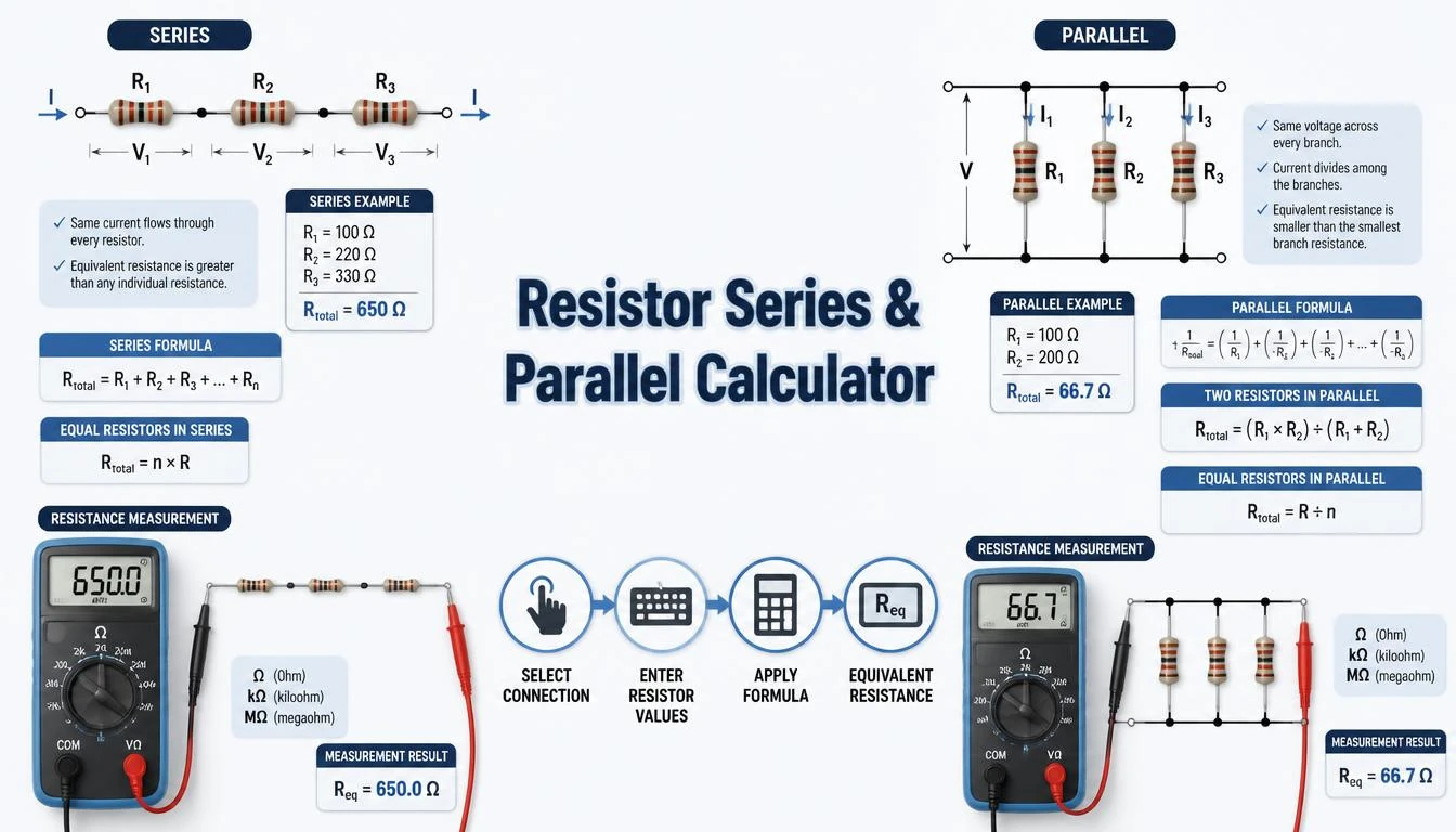
This guide explains the formulas for series and parallel resistors, unit conversions, identical-resistor shortcuts, staged network reduction, and four calculator-matched practical examples. Correct results depend on entering every resistor in consistent units and identifying the circuit connections before calculating.
What Is a Resistor Series Parallel Calculator?
A Resistor Series Parallel Calculator reduces a group of connected resistors to one equivalent resistance. This equivalent value would draw the same total current from the source as the original resistor network when connected across the same voltage.
For a series calculation, the calculator adds the resistance values directly. For a parallel calculation, it adds their reciprocals and then calculates the reciprocal of that result. A combined network must be reduced one supported series or parallel group at a time, with each equivalent value re-entered for the next stage.
Common inputs include individual resistor values and their units, such as ohms, kilohms, or megohms. The primary output is equivalent resistance, but a suitable calculator may also determine total current, branch current, voltage drop, and theoretical resistor power when a source voltage is provided.
How Does a Resistor Series Parallel Calculator Work?
The calculator applies the formula that matches the selected connection. Resistors are in series when the same current passes through each resistor sequentially without another current path at their common nodes. Resistors are in parallel when both terminals of every resistor connect to the same two electrical nodes.
- Select Series or Parallel to match the resistor connection.
- Enter each resistor value.
- Select the correct unit for every resistance.
- Add or remove resistor fields as required.
- Enter source voltage if current or power calculations are available.
- Calculate and review the equivalent resistance and related results.
The calculated equivalent resistance does not automatically determine a suitable resistor part number or power rating. Final component selection must also consider tolerance, power dissipation, voltage rating, temperature coefficient, pulse loading, ambient temperature, PCB spacing, reliability requirements, and manufacturer documentation.
Step-by-Step Process
- Inspect the circuit and identify the two nodes between which you need the equivalent resistance.
- Confirm which resistors are genuinely connected in series or parallel.
- Select the corresponding calculator mode.
- Enter each resistor value without including the unit symbol in the numerical field.
- Select ohms, kilohms, or megohms for every entered value.
- Convert all values to a common unit when calculating manually.
- Calculate the equivalent resistance.
- For a mixed circuit, simplify one definite series or parallel group at a time.
- Use Ohm’s law separately if total current, branch current, or voltage drop is required.
- Check individual resistor power and voltage stress before choosing components.
Resistor Series Parallel Calculator Formula
The equivalent resistance formula depends on how the resistors are connected. Series resistances add directly, while parallel resistances combine through their reciprocal values.
Resistors in Series Formula
Req = R1 + R2 + R3 + … + Rn
The same current flows through every resistor in a true series connection. The equivalent resistance is therefore the sum of all individual resistances and is always greater than any single resistance in the series group.
VT = V1 + V2 + V3 + … + Vn
IT = I1 = I2 = I3 = … = In
The source voltage is divided among the series resistors according to their resistance values. You can calculate each voltage drop using V = I × R.
Resistors in Parallel Formula
1 ÷ Req = (1 ÷ R1) + (1 ÷ R2) + (1 ÷ R3) + … + (1 ÷ Rn)
The same voltage appears across every resistor in a true parallel connection. Total current is the sum of the individual branch currents. The equivalent resistance of a parallel network is always lower than the smallest resistor in that network, provided all resistance values are positive and finite.
VT = V1 = V2 = V3 = … = Vn
IT = I1 + I2 + I3 + … + In
Two Resistors in Parallel
Req = (R1 × R2) ÷ (R1 + R2)
This product-over-sum formula is a convenient shortcut for exactly two parallel resistors. It should not be applied directly to three or more resistors unless the network is reduced in stages.
Identical Resistors in Series
Req = n × R
When all series resistors have the same value, multiply one resistor value by the number of resistors.
Identical Resistors in Parallel
Req = R ÷ n
When all parallel resistors have the same value, divide one resistance value by the number of resistors. For example, four 1 kΩ resistors connected in parallel have an equivalent resistance of 250 Ω.
Mixed Series-Parallel Networks
A mixed resistor network must be simplified one recognizable group at a time. Calculate the equivalent resistance of an inner series or parallel group, replace that group with its equivalent value, and repeat the process until only one resistance remains.
Req = R1 + (R2 ∥ R3)
R2 ∥ R3 = (R2 × R3) ÷ (R2 + R3)
This example represents one resistor in series with two parallel resistors. More complex bridge networks cannot always be reduced using only simple series and parallel formulas and may require nodal analysis, mesh analysis, or a suitable circuit-simulation method.
Resistance Unit Conversions
1 kΩ = 1,000 Ω
1 MΩ = 1,000 kΩ = 1,000,000 Ω
1 Ω = 0.001 kΩ = 0.000001 MΩ
All resistance values must use the same unit before you add, multiply, or divide them manually. A calculator with independent unit selectors should convert each entered value internally before applying the selected formula.
Current, Voltage, and Power Formulas
I = V ÷ R
V = I × R
P = V × I = I² × R = V² ÷ R
Equivalent resistance can be used with Ohm’s law to calculate total circuit current. Individual resistor power must still be calculated from the current through or voltage across each resistor. Total equivalent resistance alone is not sufficient for choosing the wattage rating of every component.
Formula Explanation
| Symbol | Description |
|---|---|
| Req | Equivalent or total resistance in ohms, kilohms, or megohms |
| R1, R2, R3 | Individual resistor values expressed in consistent resistance units |
| Rn | Final individual resistance in a group containing n resistors |
| n | Number of identical resistors in the connection |
| VT | Total source voltage in volts |
| V1, V2, V3 | Voltage across each resistor in volts |
| IT | Total circuit current in amperes |
| I1, I2, I3 | Current through each resistor or parallel branch in amperes |
| P | Electrical power dissipated in watts |
| Ω | Ohm, the SI unit of electrical resistance |
| kΩ | Kilohm, equal to 1,000 ohms |
| MΩ | Megohm, equal to 1,000,000 ohms |
| ∥ | Notation indicating that resistance values are connected in parallel |
Interactive Resistor Series Parallel Calculator
Use the calculator below to enter the required resistor values and obtain the calculated equivalent resistance.
Calculate equivalent resistance for multiple resistors in series or parallel. Enter values and press Calculate.⚡ Resistor Series & Parallel Calculator
Resistor Series & Parallel Result
Series: RT = R1 + R2 + …
Parallel: 1/RT = 1/R1 + 1/R2 + …
Example 1 – Calculate Series Resistance
Three resistors with values of 100 Ω, 220 Ω, and 330 Ω are connected in series across a 12 V DC source. Calculate their equivalent resistance and circuit current.
Given: R1 = 100 Ω, R2 = 220 Ω, R3 = 330 Ω and V = 12 V
Formula: Req = R1 + R2 + R3
Equivalent resistance: Req = 100 + 220 + 330 = 650 Ω
Total current: I = 12 ÷ 650 = 0.01846 A
Final result: Req = 650 Ω and I ≈ 18.46 mA
The same current flows through all three resistors. Their voltage drops will differ according to their resistance values, but the sum of those voltage drops should equal the 12 V source voltage.
Example 2 – Calculate Two Parallel Resistors
A 1 kΩ resistor and a 2.2 kΩ resistor are connected in parallel across a 12 V DC supply. Calculate the equivalent resistance and total current.
Unit conversion: 1 kΩ = 1,000 Ω and 2.2 kΩ = 2,200 Ω
Formula: Req = (R1 × R2) ÷ (R1 + R2)
Calculation: Req = (1,000 × 2,200) ÷ (1,000 + 2,200)
Equivalent resistance: Req = 2,200,000 ÷ 3,200 = 687.5 Ω
Total current: IT = 12 ÷ 687.5 ≈ 0.01745 A
Final result: Req = 687.5 Ω and IT ≈ 17.45 mA
The equivalent resistance is lower than 1 kΩ, which is the smaller branch resistance. Each resistor receives the full 12 V because both branches are connected across the same two nodes.
Example 3 – Calculate Three Parallel Resistors
Three resistors of 330 Ω, 470 Ω, and 1 kΩ are connected in parallel. Calculate their total equivalent resistance.
Unit conversion: 1 kΩ = 1,000 Ω
Formula: 1 ÷ Req = (1 ÷ 330) + (1 ÷ 470) + (1 ÷ 1,000)
Calculation: 1 ÷ Req ≈ 0.003030 + 0.002128 + 0.001000
1 ÷ Req ≈ 0.006158
Final result: Req ≈ 162.39 Ω
The result is lower than 330 Ω, confirming the expected behavior of a parallel network. Rounding should normally be delayed until the final step to avoid unnecessary calculation error.
Example 4 – Calculate Four Identical Parallel Resistors
Four 1 kΩ resistors are connected in parallel across a 12 V DC supply. In the calculator, select Parallel and enter 1000, 1000, 1000, 1000.
Formula: Req = R ÷ n
Equivalent resistance: Req = 1,000 ÷ 4 = 250 Ω
Total current: IT = 12 ÷ 250 = 0.048 A = 48 mA
Branch current: I = 12 ÷ 1,000 = 12 mA per resistor
Final result: The calculator returns 250 Ω. Four equal branches each carry 12 mA, giving 48 mA total.
Practical Field Considerations for Resistor Networks
Circuit topology must be identified before using the calculator. Two resistors drawn beside one another are not necessarily parallel, and two components that appear sequentially are not necessarily in series. Parallel components must share both electrical nodes, while a pure series junction must not provide another current path.
Resistor tolerance affects the actual equivalent resistance. A resistor marked 1 kΩ with a ±5% tolerance may have a measured value between its permitted limits. When circuit accuracy matters, calculate worst-case combinations or use measured values and suitably specified precision resistors.
Resistance can change with temperature. Each component’s temperature coefficient, self-heating, ambient temperature, ventilation, and proximity to other heat-producing parts can affect the operating value. These effects are especially important in precision measurement, sensing, timing, feedback, and reference circuits.
Power sharing must be checked separately. Series resistors carry the same current but may dissipate different power because their resistance values differ. Parallel resistors have the same voltage but may carry different currents and dissipate different power.
Before measuring resistance with a multimeter, isolate and de-energize the circuit according to appropriate safety procedures. Other connected components can create parallel paths that change the displayed measurement, while charged capacitors or an energized circuit can create hazards and unreliable readings.
Applications of a Resistor Series-Parallel Calculator
Electronics Design Applications
- Combining available resistor values to obtain a required resistance.
- Designing bias, pull-up, pull-down, and feedback networks.
- Reviewing voltage-divider and current-limiting circuits.
- Estimating equivalent loads connected to a circuit output.
Industrial and Automation Applications
- Designing PLC input and output interface networks.
- Checking sensor signal-conditioning circuits.
- Combining termination, burden, or current-limiting resistors.
- Reviewing control-panel indication and alarm circuits.
Maintenance Applications
- Comparing measured resistance with a circuit’s expected value.
- Checking the effect of an open or shorted resistor.
- Finding replacement combinations when one exact value is unavailable.
- Supporting troubleshooting of resistor networks and PCB assemblies.
Educational Applications
- Learning the difference between series and parallel connections.
- Practising equivalent-resistance calculations.
- Verifying Ohm’s law exercises.
- Studying current paths, voltage drops, and power dissipation.
Advantages of a Resistor Series-Parallel Calculator
- Reduces repetitive reciprocal calculations.
- Calculates series and parallel equivalent resistance.
- Supports consistent resistance-unit conversion.
- Helps compare alternative resistor combinations.
- Supports preliminary circuit analysis and troubleshooting.
- Helps verify manual calculation results.
- Demonstrates how circuit topology affects total resistance.
- Provides a useful learning tool for electrical and electronics students.
Limitations
- The result depends on entering the correct circuit arrangement.
- Nominal resistor values do not include actual tolerance variation.
- Temperature and self-heating can change resistance.
- Simple formulas may not reduce bridge or complex multi-node networks.
- Equivalent resistance does not determine individual resistor power ratings.
- Parasitic capacitance and inductance may matter at high frequencies.
- Connected components can affect in-circuit resistance measurements.
- The calculator does not replace manufacturer specifications or professional circuit analysis.
Common Mistakes
- Adding parallel resistor values directly.
- Using the product-over-sum shortcut for more than two resistors.
- Mixing Ω, kΩ, and MΩ without conversion.
- Assuming components are parallel because they appear side by side.
- Assuming components are in series when another current path exists.
- Rounding reciprocal values too early.
- Ignoring resistor tolerance and temperature coefficient.
- Using total equivalent resistance as the rating of every resistor.
- Ignoring individual voltage and power stress.
- Measuring resistance in an energized or non-isolated circuit.
Verify individual resistor values with the Resistor Color Code Calculator and calculate LED series resistance with the LED Resistor Calculator.
Frequently Asked Questions
What is a Resistor Series Parallel Calculator?
It calculates the equivalent resistance of resistors connected in series or parallel arrangements.
How do I calculate resistors in series?
Add all individual resistance values. The equivalent resistance is Req = R1 + R2 + … + Rn.
How do I calculate resistors in parallel?
Add the reciprocal of every resistance and take the reciprocal of the total: 1 ÷ Req = 1 ÷ R1 + 1 ÷ R2 + … + 1 ÷ Rn.
Why is parallel resistance lower than the smallest resistor?
Adding parallel branches creates additional current paths. The source therefore sees greater total conductance and lower equivalent resistance.
Can I mix ohms and kilohms in one calculation?
Yes, if the calculator converts each selected unit correctly. For manual calculations, first convert all resistor values to the same unit.
Does equivalent resistance determine resistor wattage?
No. Calculate the voltage, current, and power of each resistor separately, then select appropriate component ratings using manufacturer information and a suitable margin.
Can every resistor network be reduced using these formulas?
No. Simple series and parallel networks can be reduced directly, but bridge and complex multi-node circuits may require other circuit-analysis methods.
Why can measured resistance differ from the calculated value?
Differences can result from component tolerance, temperature, meter accuracy, lead resistance, damaged components, or parallel paths through other connected parts.
Related Tech Volt Lab Resources
Helpful Electrical Engineering Resources
Final Thoughts
A Resistor Series Parallel Calculator determines the equivalent resistance of series, parallel, and supported mixed resistor networks. It applies the appropriate formula to consistent resistance values and can support additional current, voltage, and power calculations.
The result is useful for electronics design, PLC interfaces, sensor circuits, control panels, maintenance work, education, and troubleshooting. Accurate analysis still requires correct identification of circuit nodes, suitable unit conversions, and separate checks for individual component stress.
Use the Resistor Series Parallel Calculator from Tech Volt Lab as a practical calculation and verification tool. Before finalizing a circuit, compare the results with measured values, resistor tolerances, power requirements, environmental conditions, and component manufacturer documentation.
Explore More Engineering Calculators
Discover more free electrical and automation calculators designed for electricians, PLC programmers, maintenance technicians, and engineers.
View All Calculators